
Pressing and fixing device for workpiece deburring

A fixing device and deburring technology, used in machine tools suitable for grinding workpiece edges, grinding workpiece supports, manufacturing tools, etc. glitches etc.

Inactive Publication Date: 2021-07-30
徐敏旺
View PDF0 Cites 0 Cited by
  • Summary
  • Abstract
  • Description
  • Claims
  • Application Information

AI Technical Summary

Problems solved by technology

[0002] Extra burrs are often produced during the processing of mechanical parts, such as millimeter-scale casting burrs at the joints of the mold or at the root of the gate, and burrs on mechanical parts. Some are caused by plastic deformation during cutting, and some It is the flash of casting, die forging, etc., and some of it is the residual material of welding extrusion. In the process of deburring, it is often completed by using the deburring machine and the pressing and fixing device for the workpiece. However, the traditional The compression and fixing device used for workpiece deburring is often used to compress and fix the workpiece through clamping and fixing devices such as bolts and nuts. In the process of deburring the workpiece, the traditional compression and fixing device compresses the workpiece It is difficult to disassemble it when it is fixed, which makes it difficult to remove the burrs around the compression fixture, which in turn makes it more laborious to deburr the workpiece in an all-round way; secondly, because the compression fixture compresses the surface of the workpiece, it is impossible to polish the compression part Burrs often need to be polished and deburred at the pressing position after removing the pressing and fixing device, which is inconvenient to operate and increases the workload

Method used


Image

  • Pressing and fixing device for workpiece deburring
  • Pressing and fixing device for workpiece deburring
  • Pressing and fixing device for workpiece deburring

Examples


Embodiment Construction

[0024] The following will clearly and completely describe the technical solutions in the embodiments of the present invention with reference to the accompanying drawings in the embodiments of the present invention. Obviously, the described embodiments are only some, not all, embodiments of the present invention. Based on the embodiments of the present invention, all other embodiments obtained by persons of ordinary skill in the art without making creative efforts belong to the protection scope of the present invention.

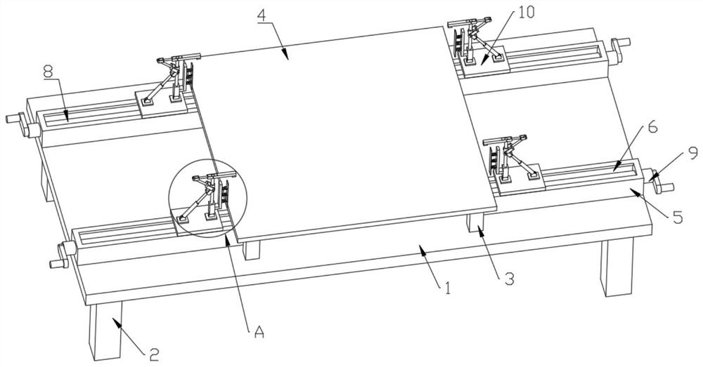
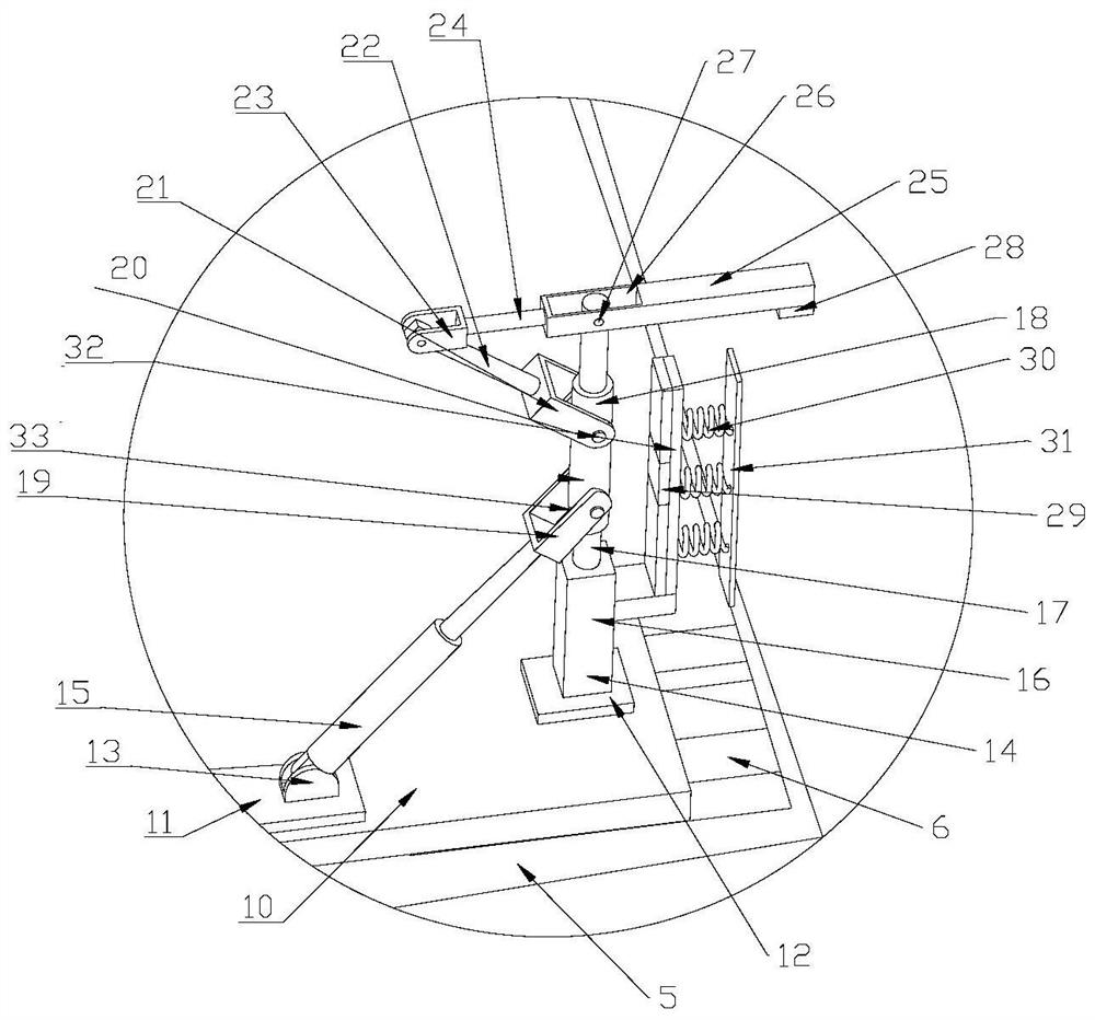
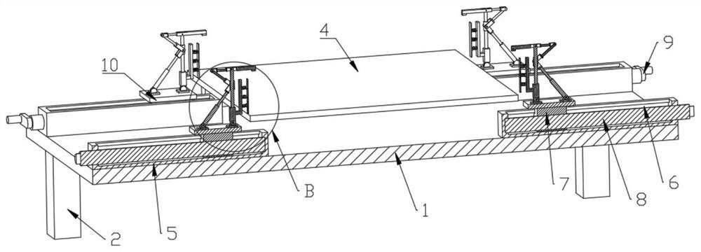
[0025] like Figure 1 to Figure 6 As shown, the present invention provides a pressing and fixing device for workpiece deburring, including a workbench 1, the lower end of the workbench 1 is fixedly connected with a support leg 2, the upper end of the workbench 1 is provided with a controller, and the upper end of the workbench 1 is fixedly connected with a The support column 3 is fixedly connected with the support plate 4 at the upper end of the support column...


PUM


Abstract

The invention belongs to the technical field of pressing and fixing, and discloses a pressing and fixing device for workpiece deburring. The pressing and fixing device comprises a workbench, wherein supporting legs are fixedly connected to the lower end of the workbench, a controller is arranged at the upper end of the workbench, supporting columns are fixedly connected to the upper end of the workbench, a supporting plate is fixedly connected to the upper ends of the supporting columns, sliding rails are fixedly connected to the upper end of the workbench, sliding grooves are formed in the upper ends of the sliding rails, sliding blocks are slidably connected into the sliding grooves, threaded columns are in threaded connection with the interiors of the sliding blocks, and the threaded columns are fixedly connected to output shafts of stepping motors. According to the pressing and fixing device for the workpiece deburring, a sleeve moves upwards by adjusting an electric telescopic rod, and a second linkage rod rotates under the action of a first linkage rod, so that a rotating rod rotates with a second rotating shaft as the axis, and then a clamping block at the lower end of the rotating rod presses and fixes a workpiece.

Description

technical field [0001] The invention belongs to the technical field of compression and fixing, in particular to a compression and fixing device for deburring workpieces. Background technique [0002] Extra burrs are often produced during the processing of mechanical parts, such as millimeter-scale casting burrs at the joints of the mold or at the root of the gate, and burrs on mechanical parts. Some are caused by plastic deformation during cutting, and some It is the flash of casting, die forging, etc., and some of it is the residual material of welding extrusion. In the process of deburring, it is often completed by using the deburring machine and the pressing and fixing device for the workpiece. However, the traditional The compression and fixing device used for workpiece deburring is often used to compress and fix the workpiece through clamping and fixing devices such as bolts and nuts. In the process of deburring the workpiece, the traditional compression and fixing devi...

Claims


Application Information

Patent Timeline
IPC IPC(8): B24B41/06B24B9/04
CPCB24B9/04B24B41/06
Inventor 徐敏旺
Owner 徐敏旺
Learn More