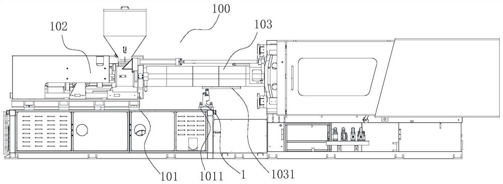
[0002] Injection platform parts of large and medium-sized injection molding machines need to move back and forth under the drive of the injection platform moving cylinder during equipment debugging or maintenance, such as replacing the inner parts of the melt cylinder; The
cantilever beam is very heavy, which causes the center of gravity of the entire injection platform to shift outward; and the gap between the guide rod and the
copper sleeve of the injection platform, which is the moving guide structure of the injection platform components, is assembled by clearance fit. Therefore, when the center of gravity of the injection platform moves outward, the problem of sagging of the melted rubber tube (the larger the gap value, the greater the sag) will inevitably occur. At the same time, because the melted rubber tube is a long
cantilever beam, its own weight will also This causes it to bend and deform, which increases the sag at the end of the melt tube, and causes a deviation in the alignment accuracy of the
nozzle installed at the end of the melt tube and the mold mouth of the clamping part, resulting in a deviation in the
machine's injection process. , it is easy to leak glue at the glue port; at the same time, because the overall center of gravity of the injection platform is offset, the overturning moment will be generated along the axial direction of the guide rod of the injection platform. wear, thereby reducing the
motion accuracy of the injection platform, affecting the injection performance, and accelerating the damage and failure of
moving parts, especially for models with a relatively large screw length and
diameter, the extension length of the melt cylinder is particularly large, and it is even more necessary to install the injection
molding machine under the melt cylinder. Platform support structure to support its offset weight, ensure the horizontal and smooth movement of the injection platform, prevent the melt cylinder from sagging, and ensure the normal movement and service life of the
moving parts;
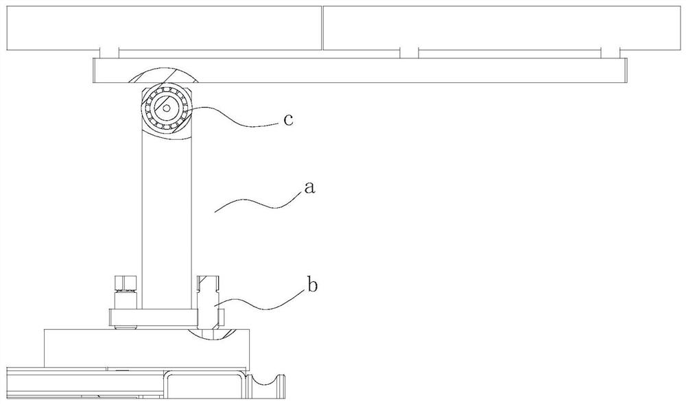
[0003] like figure 1 As shown, the rigid support part a is currently used in the industry. The method of installation and commissioning of the rigid support part a is: move the injection platform to the rearmost end (a position away from the mold clamping part), and then place the rigid support part a on the predetermined At the installation position, manually adjust the height adjustment screw b of the supporting part, so that the supporting wheel c is just in contact with the supporting guide rail of the injection platform; after such a supporting mechanism is installed according to the above installation method, there are two obvious problems as follows: 1. Due to its The installation standard is that the support wheel c is just in contact with the support rail of the injection platform, the
contact force will be very small, and there is not enough support rigidity, which will result in hundreds of kilograms of melted plastic cylinder parts, and the support force provided by the support mechanism is only a few kilograms or tens of kilograms , it has almost no supporting effect on the parts of the melted rubber cylinder; 2. Since the melted rubber cylinder, the support guide rail of the injection platform and the related parts of the injection platform have more or less
processing errors, there will be a large tolerance after they are assembled together Cumulatively, it is impossible to guarantee that the position of the support rail of the injection platform is horizontal after installation. In this way, objectively, the support guide rail of the injection platform will have a drooping angle relative to the horizontal line. When the support wheel c is just in contact with the guide rail at the rear end, the support wheel c The
height difference between c and the support guide rail is zero, but after the injection platform moves forward for a certain distance, it will be found that the support wheel c and the support guide rail are disengaged, and there is a stepping gap. At this time, the injection platform guide rail appears in a state of no support force. The support mechanism of the injection platform can not play a supporting role at all

