Sludge low-temperature drying treatment device and treatment method

A treatment device and drying device technology, applied in dehydration/drying/concentrated sludge treatment, chemical instruments and methods, separation methods, etc., can solve problems such as shortened service life, leakage of heating device, easy adhesion, etc.

Active Publication Date: 2021-07-30
浙江锦寰环保科技有限公司
View PDF7 Cites 0 Cited by
  • Summary
  • Abstract
  • Description
  • Claims
  • Application Information

AI Technical Summary

Problems solved by technology

However, in the current low-temperature sludge drying treatment method, only the side where the sludge is in contact with dry and hot air can be effectively dried, and the sludge inside cannot be effectively dried during the process of sludge being transported.
In addition, due to the uneven dryness and wetness of the sludge, the sludge easily adheres to the conveying device, causing the mesh on the conveying device to be clogged, and the accumulated sludge continues to accumulate and harden or fall off, affecting the ventilation effect
Moreover, most of the drying devices are in direct contact with the air in the device, and the condensed water accumulates in the integrated equipment, which is easy to enter the water, causing leakage and rust of the heating device and other equipment, and shortening the service life

Method used


Image

  • Sludge low-temperature drying treatment device and treatment method
  • Sludge low-temperature drying treatment device and treatment method
  • Sludge low-temperature drying treatment device and treatment method

Examples


Embodiment Construction

[0067] The following description serves to disclose the present invention to enable those skilled in the art to carry out the present invention. The preferred embodiments described below are only examples, and those skilled in the art can devise other obvious variations.

[0068] In order to solve the technical problems of sludge low-temperature drying treatment, such as figure 1 , figure 2 , image 3 As shown, the following technical solutions are provided:

[0069] A sludge low-temperature drying treatment device, comprising:

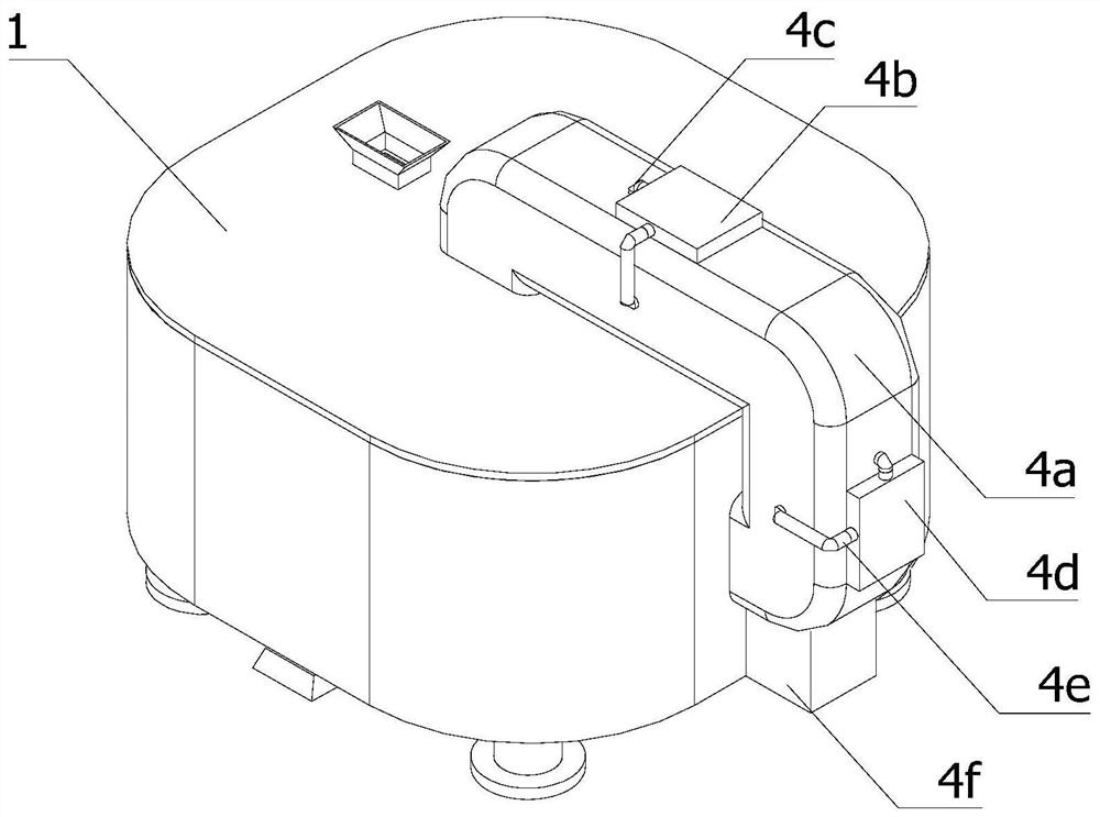
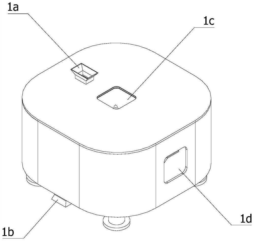
[0070] An incubator 1, the top of the incubator 1 is provided with a feed port 1a, and the bottom of the incubator 1 is provided with a discharge port 1b, and the incubator 1 is used to avoid rapid loss of internal heat energy;

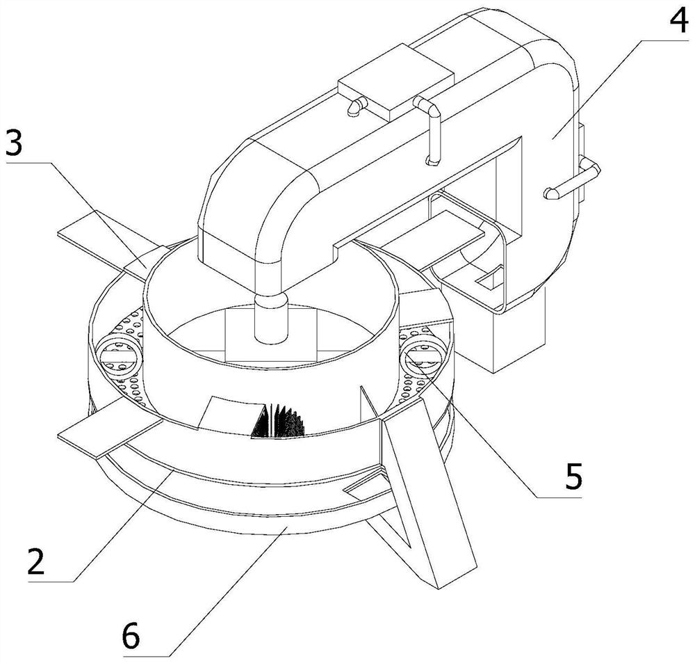
[0071] Rotating device 2, the rotating device 2 is installed on the inner wall of the bottom of the incubator 1, and the rotating device 2 is used to rotate and transfer the sludge;

[0072] The unloading device 3, the ...


PUM


Abstract

The invention relates to the field of low-temperature drying machine equipment, in particular to a sludge low-temperature drying treatment device. The device comprises: a heat preservation box provided with a feeding port and a discharging port. a rotating device which is mounted on the inner wall of the bottom of the heat preservation box; a discharging device, wherein the output end of the discharging device is communicated with the discharging opening of the heat preservation box, and the discharging device is used for discharging the dried sludge; a drying device which is used for heating and drying air in the heat preservation box; a stirring device which is arranged in the discharging device, and is used for stirring the sludge on the rotating device; and a cleaning device, wherein the two working ends of the cleaning device are located at the upper end and the lower end of the rotating device respectively, and the cleaning device is used for cleaning redundant sludge on the rotating device. According to the scheme, sludge can be effectively prevented from being deposited on the rotating device, the sludge can be in full contact with dry and hot air, the drying effect is improved, and meanwhile the service life of the sludge low-temperature drying device can be prolonged.

Description

technical field [0001] The invention relates to the field of low-temperature drying machine equipment, in particular to a sludge low-temperature drying treatment device and treatment method. Background technique [0002] Sludge low-temperature drying treatment device is a new type of efficient and compact sludge treatment equipment, which is widely used in various fields. However, in the current low-temperature sludge drying treatment method, only the side where the sludge is in contact with the hot and dry air can be effectively dried, and the sludge inside cannot be effectively dried during the process of sludge being transported. In addition, due to the uneven dryness and wetness of the sludge, the sludge easily adheres to the conveying device, causing the mesh on the conveying device to be clogged, and the accumulated sludge continues to accumulate and harden or fall off, affecting the ventilation effect. Moreover, most of the drying devices are in direct contact with t...

Claims


Application Information

Patent Timeline
Patent Type & Authority Applications(China)
IPC IPC(8): C02F11/13B01D53/26B01F7/04B08B9/087
CPCC02F11/13B01D53/26B08B9/087B01D2258/06B01D2257/80B01F27/70Y02W10/37
Inventor 王庆海虞向峰余夙吴伟锋仇伟锋赵飞邵达利
Owner 浙江锦寰环保科技有限公司
Why Eureka
Try Eureka