
Reaction cavity, semiconductor process equipment and base temperature control method

A technology of reaction chamber and process equipment, applied in semiconductor/solid-state device manufacturing, metal material coating process, coating, etc., can solve the problems of inability to monitor real-time trays, easily damaged temperature calibration trays, and increase equipment costs, etc. The effect of improving temperature detection efficiency, improving temperature measurement accuracy and reducing temperature measurement error

Active Publication Date: 2021-07-30
BEIJING NAURA MICROELECTRONICS EQUIP CO LTD
View PDF11 Cites 0 Cited by
  • Summary
  • Abstract
  • Description
  • Claims
  • Application Information

AI Technical Summary

Problems solved by technology

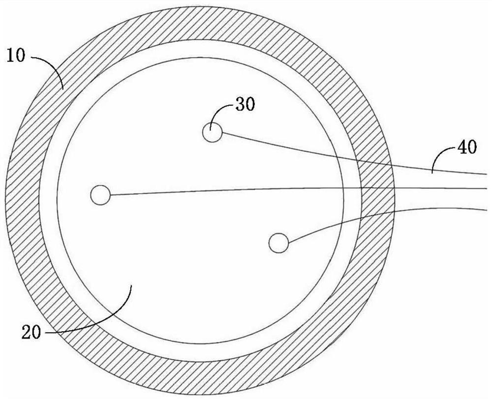
[0004] However, the above-mentioned temperature calibration tray can only be carried out when the reaction chamber is in a non-process state, but cannot monitor the temperature of the tray in real time when the reaction chamber is in a process state; On the body 10, it will hinder the rotation of the base, so it is necessary to open the cavity and remove the temperature calibration tray before the formal process, the temperature calibration efficiency is low, and it is easy to damage the temperature calibration tray during the cavity opening process, which increases the cost of the equipment

Method used


Image

  • Reaction cavity, semiconductor process equipment and base temperature control method
  • Reaction cavity, semiconductor process equipment and base temperature control method
  • Reaction cavity, semiconductor process equipment and base temperature control method

Examples


Embodiment Construction

[0035] The present invention is described in detail below, and examples of embodiments of the present invention are shown in the accompanying drawings, wherein the same or similar reference numerals denote the same or similar components or components having the same or similar functions throughout. Furthermore, detailed descriptions of known techniques are omitted if they are not necessary to illustrate the features of the invention. The embodiments described below by referring to the figures are exemplary only for explaining the present invention and should not be construed as limiting the present invention.

[0036] Those skilled in the art can understand that unless otherwise defined, all terms (including technical terms and scientific terms) used in this embodiment have the same meanings as those of ordinary skill in the art to which the present invention belongs. It should also be understood that terms, such as those defined in commonly used dictionaries, should be unders...


PUM


Abstract

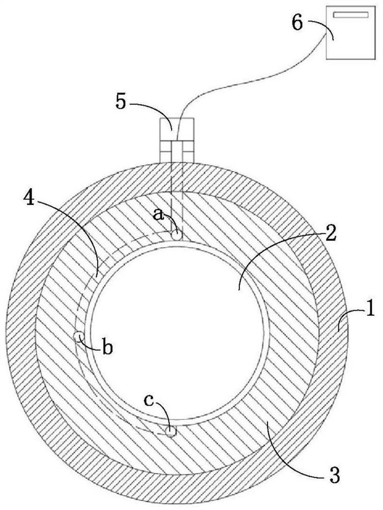
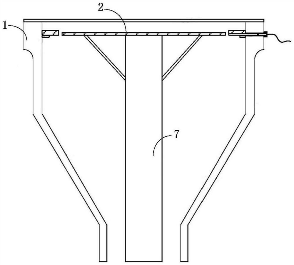
The invention provides a reaction cavity, semiconductor processing equipment and a base temperature control method. The reaction cavity comprises a cavity body, a base and a preheating ring, wherein the preheating ring is connected with the inner circumferential wall of the cavity body and surrounds the periphery of the base, the reaction cavity further comprises a temperature measuring assembly, the temperature measuring assembly comprises an arc-shaped detection pipe and a temperature measuring element arranged in the arc-shaped detection pipe, the arc-shaped detection pipe is arranged at the position, close to the inner circumferential edge of the preheating ring, of the bottom of the preheating ring and extends in the circumferential direction of the base; one end of the detection pipe is provided with an extension part, and the extension part penetrates through the cavity body and extends to the outside of the cavity body; the temperature measuring element is used for detecting the temperature of a plurality of temperature measuring points which are distributed at intervals in the extension direction of the arc-shaped detection pipe, and is used as an edge temperature value of the base, and wires of the temperature measuring element are led out of the cavity body through the extension part. According to the reaction cavity, the semiconductor processing equipment and the base temperature control method, the temperature of the base is detected in real time in the process state of the cavity, and the cavity does not need to be opened and the temperature measuring assembly does not need to be dismantled before the formal process is started.

Description

technical field [0001] The invention relates to the field of semiconductor manufacturing, in particular to a reaction chamber, semiconductor process equipment and a temperature control method for a base. Background technique [0002] The basic principle of the chemical vapor deposition epitaxial growth process is: by heating the wafer, the process gas in the reaction chamber reacts with the wafer material, and deposits a film on the surface of the wafer. In order to obtain a good epitaxial growth effect, the temperature of the wafer in the process is very important. Therefore, it is necessary to calibrate the temperature field of the reaction chamber before performing the epitaxial growth process. [0003] At present, a special calibration tray is usually used to calibrate the temperature field of the reaction chamber. Such as figure 1 As shown, the temperature calibration tray 20 is arranged on a base (not shown in the figure) in the cavity 10, and a plurality of temperat...

Claims


Application Information

Patent Timeline
IPC IPC(8): C23C16/52C23C16/46H01L21/67
CPCC23C16/52C23C16/46H01L21/67248
Inventor 徐玉凯王欢
Owner BEIJING NAURA MICROELECTRONICS EQUIP CO LTD
Learn More