Single-cylinder anti-rotation device and tunneling equipment

An anti-rotation, single-cylinder technology, applied in mining equipment, earthwork drilling, tunnels, etc., can solve the problems of easily damaged oil cylinders, and achieve the effect of simple working principle, reduced wear and low production cost

Inactive Publication Date: 2021-07-30
CHINA RAILWAY ENGINEERING EQUIPMENT GROUP CO LTD
View PDF10 Cites 1 Cited by
  • Summary
  • Abstract
  • Description
  • Claims
  • Application Information

AI Technical Summary

Problems solved by technology

[0005] The purpose of the present invention is to provide a single-cylinder anti-rotation device to solve the technical problem in the prior art that during the turning process of the shield machine, the end of the oil cylinder is easily damaged by the pressure of the inner wall of the tail shield on the oil cylinder; the present invention The purpose is also to provide a tunneling equipment

Method used


Image

  • Single-cylinder anti-rotation device and tunneling equipment
  • Single-cylinder anti-rotation device and tunneling equipment
  • Single-cylinder anti-rotation device and tunneling equipment

Examples


Embodiment 1

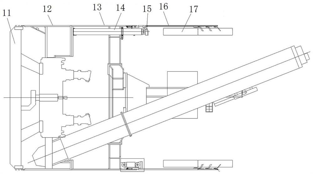
[0062] Prior to the introduction of the single cylinder anti-rotation device of the present invention, the structure of the prior art in the prior art, such as figure 1 As shown, the shield machine includes the front shield 12, the medium shield 13, and the tail shield 16. The front portion of the front shield 12 is provided with a cutter disk 11, and the medium shield 13 is fixed with a propulsion cylinder 14, and the telescopic rod of the cylinder 14 is propelled. There is a cylinder booth 15; the mounting of the tubic sheet 17 is carried out under the protection of the tail shield 16, and after the installation of each cyclic piece 17 is installed, the telescopic rod of the cylinder 14 projects, the cylinder head on the telescopic rod is pressed. On the mounted tube 17, the reaction force provided by the tube 17 is provided so that the shield is moved forward.

[0063] due to figure 1 The anti-rotation structure is not provided on the cylinder booth 15, and therefore, the teles...

Embodiment 2

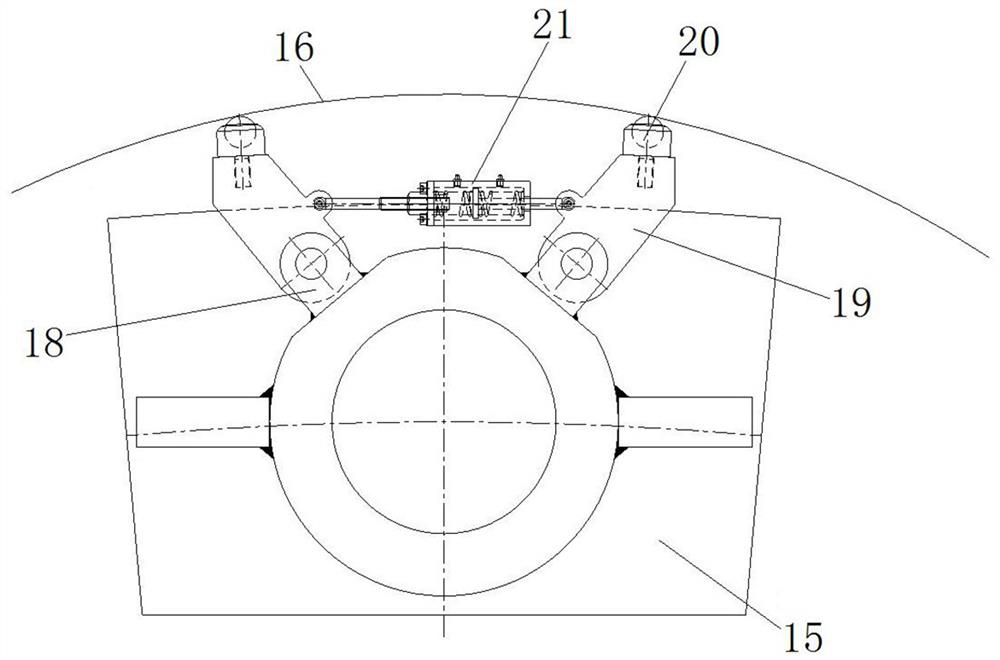
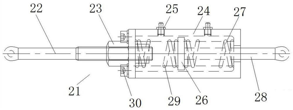
[0076] The difference from the first embodiment is that the first connection arm 22 is fixed to the sleeve 24 in the first connection arm 22, and the second connection arm 28 is slidably fitted in the sleeve 24, passed through the second connection arm 28 in the set. Slide in the cartridge 24 to achieve an angle change between the two connectors. In this embodiment, the first and second connections are slidably fitted within the sleeve, and the crossing arm is slid in the sleeve to achieve the angle change between the two connectors.

Embodiment 3

[0078] The difference from the first embodiment is that in the first embodiment, the first connection arm 22 has a threaded segment, and the first connection arm 22 is threaded on the sleeve 24 to regulate its axial position in the sleeve 24, and When the first connection arm 22 is adjusted to the sleeve 24 after the lock nut 23 is adjusted. In this embodiment, a planar surface is provided on the first connection arm, and a tight screw is provided, and the tight screw is adjusted radially in the sleeve. The first connecting arm is adjusted to the end cover by tightening the screw after adjustment. .


PUM


Abstract

The invention relates to a single-cylinder anti-rotation device and tunneling equipment. The single-cylinder anti-rotation device comprises an oil cylinder supporting shoe, two supporting arms and an elastic telescopic structure, wherein the two supporting arms are both hinged to the oil cylinder supporting shoe, the ends, away from the oil cylinder supporting shoe, of the supporting arms are provided with supporting parts, and the supporting parts are used for being supported on the inner wall of a shield body; the elastic telescopic structure is arranged between the two supporting arms, the elastic telescopic structure comprises a sleeve and two connecting arms, wherein a sliding disc is assembled in the sleeve in a sliding mode, elastic pieces are arranged at the positions, on the two sides of the sliding disc, in the sleeve, and the two elastic pieces apply opposite elastic acting force to the sliding disc; and one ends of the two connecting arms are hinged to the corresponding supporting arms respectively, and the other ends of the two connecting arms are connected with the sliding disc so as to be assembled in the sleeve in a sliding mode. The included angle between the two supporting arms is adjusted in a self-adaptive mode through the elastic telescopic structure so as to adjust the interaction force between the supporting arms and the inner wall of a tail shield, and the risks that the inner wall of the tail shield is abraded and the end of a thrust oil cylinder is pressed and damaged are reduced.

Description

Technical field [0001] The present invention relates to a single-cylinder anti-rotation device and a tractor device. Background technique [0002] Shield construction is widely used due to efficient, safe, impact on surrounding environment, so it has been widely used. The installation of the tube sheet in the shield is carried out under the protection of the tail shield housing, and after the installation of each cyclic piece is installed, the host is advanced by the advancement of the mounted tube. Propencing the cylinder with an air push stroke in front of the contact tube, during the air push, the single cylinder is generally reversed, and the area of ​​the cylinder head contact tube will result in small, increase the pneumatizing tube after the single cylinder is twisted. The risk of the film; at the same time, after a certain degree of torsion in a single cylinder, the cylinder booth is in contact with the inner wall of the tail shield housing, increasing the risk of the har...

Claims


Application Information

Patent Timeline
Patent Type & Authority Applications(China)
IPC IPC(8): E21D9/06E21D9/087
CPCE21D9/0621E21D9/0873
Inventor 马钢建王昆白岩龙郑亮奎闫阳翟聪袁文征高文梁郑康泰
Owner CHINA RAILWAY ENGINEERING EQUIPMENT GROUP CO LTD
Why Eureka
Try Eureka