Urine flow velocity and flow identification method

A flow recognition, urine flow technology, applied in the field of biomedicine

Pending Publication Date: 2021-07-30
YOOTANE TECH (TAIZHOU) CO LTD
View PDF10 Cites 1 Cited by
  • Summary
  • Abstract
  • Description
  • Claims
  • Application Information

AI Technical Summary

Problems solved by technology

[0002] The flow rate and flow rate of urine usually reflect some health conditions of the human body. At the same time, in the process of automatic urine detection, the flow rate and flow rate of urine can be used to assist in judging the health status of the human body. However, in the prior art, there is a lack of a The technology of real-time detection of urine flow velocity and flow rate can detect urine flow velocity and flow rate in real time during the sampling process

Method used


Image

  • Urine flow velocity and flow identification method
  • Urine flow velocity and flow identification method
  • Urine flow velocity and flow identification method

Examples


Embodiment 1

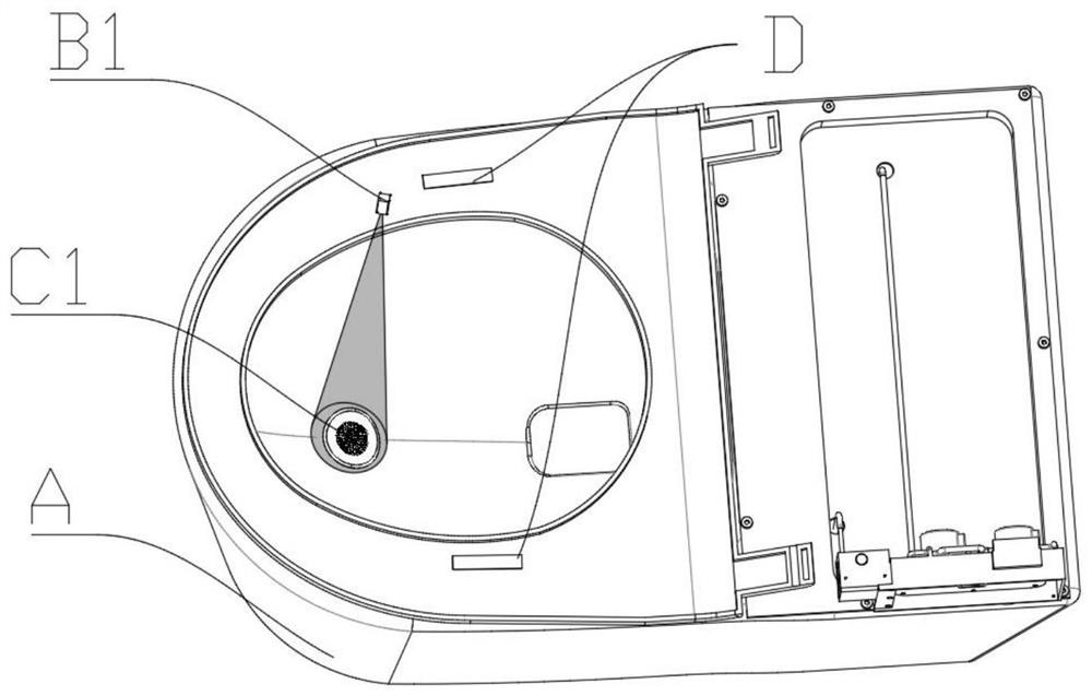
[0045] Such as figure 1 , a urine single-point detection sampling system, comprising a sampling toilet A, the sampling toilet is provided with a urine identification sensor, where the urine identification sensor is set as a temperature sensor B1, and a urine identification sensor is provided below the temperature sensor B1 Sampling device, the urine sampling device in this embodiment is set as a urine sampling valve C1, the urine sampling valve C1 is set on the inner wall of the front part of the toilet, and the sensing range of the temperature sensor B1 covers the urine Sampling valve.

[0046] Further, the temperature sensor B1 is set as an infrared temperature sensor, and the infrared temperature sensor is set on the side of the toilet lid of the sampling toilet, and the infrared temperature sensor emits at least one beam of red light to the urine sampling valve for Sensing whether urine is set at the sampling valve.

[0047] Further, a pressure sensor D is provided on th...

Embodiment 2

[0074] Embodiment two:

[0075] In this example, if Figure 11 , providing a toilet detection device in another way, the sampling toilet is provided with a toilet cover, the toilet cover includes a toilet gasket, a toilet seat is provided above the toilet gasket, and an arc-shaped Sampling rod F, the end of the arc-shaped sampling rod F is provided with a rotating power mechanism F1 to drive the arc-shaped sampling rod to rotate up and down, and the arc-shaped sampling rod is provided with a sampling port F2, and the sampling port F2 passes through The sampling micropump is connected to the urine detection device;

[0076] The toilet gasket is provided with a urine trajectory imaging sensor B2, and the urine trajectory imaging sensor B2 collects information under the toilet gasket.

[0077] Further, the urine trajectory imaging sensor B2 is set as a thermal imaging camera.

[0078] In this embodiment, it is set as a thermal imaging camera, and in other embodiments, it can a...

Embodiment 3

[0097] In addition to the above two embodiments, the present invention also provides a third embodiment: as Figure 17 , a urine detection toilet lid, comprising a toilet gasket, the toilet lid gasket is provided with a first urine trajectory imaging sensor B4 on one side of the toilet gasket, and the front end of the toilet lid gasket is also provided with a second urine Trajectory imaging sensor B5; a mechanical arm sampling rod F3 is arranged under the toilet gasket. A third urine track imaging sensor B6 is also arranged on the toilet lid gasket, and the third urine track imaging sensor B6 is arranged opposite to the first urine track imaging sensor B4. In this embodiment, the urine trajectory imaging sensor is set in this way. In other embodiments, the urine trajectory imaging sensor can also be located in different positions, such as using only one sensor to place in the toilet, or using two sensors to place in the toilet The opposite sides, as long as the same effect ca...


PUM


Abstract

The invention relates to the field of biological detection, in particular to a urine flow velocity and flow identification method, which comprises the following steps of: 1) shooting urine flow in a closestool in real time through a urine imaging sensor, reading a video stream, processing each frame of data, performing difference comparison on each frame of a video and an original state through a frame difference method, and recording urine flowing initial time and position; 2) tracking the shape and the movement track of the urine through a thermal imaging sensor, and determining a tracking point; and 3) calculating the speed of the tracking point according to the initial time and the position difference of the tracking point to obtain the urine flow rate. According to the urine flow rate and flow rate identification method, through video processing, the urine flow rate and flow rate in the urine detection closestool sampling process can be effectively identified, and then the health condition of a user is identified and monitored according to the urine flow rate and flow rate of the user.

Description

technical field [0001] The invention relates to the field of biomedicine, in particular to a method for identifying urine flow rate and flow. Background technique [0002] The flow rate and flow rate of urine usually reflect some health conditions of the human body. At the same time, in the process of automatic urine detection, the flow rate and flow rate of urine can be used to assist in judging the health status of the human body. However, in the prior art, there is a lack of a The technology for real-time detection of urine flow velocity and flow rate can detect urine flow velocity and flow rate in real time during the sampling process. Contents of the invention [0003] The object of the present invention is: a technology for real-time detection of urine flow velocity and flow, which can detect urine flow velocity and flow in real time during the sampling process. [0004] The technical solution of the present invention is: a urine flow velocity and flow identificatio...

Claims


Application Information

Patent Timeline
Patent Type & Authority Applications(China)
IPC IPC(8): G01D21/02
CPCG01D21/02
Inventor 闵浩迪
Owner YOOTANE TECH (TAIZHOU) CO LTD
Why Eureka
Try Eureka