Crankshaft rotating speed sensor positioning tool

A technology of crankshaft speed and sensors, which is applied in the direction of instruments, linear/angular velocity measurement, velocity/acceleration/shock measurement, etc. It can solve problems affecting engine production, loss of positioning, guiding function, and imprecise positioning process, etc.

Pending Publication Date: 2021-07-30
GUANGXI YUCHAI MASCH CO LTD
View PDF0 Cites 3 Cited by
  • Summary
  • Abstract
  • Description
  • Claims
  • Application Information

AI Technical Summary

Problems solved by technology

[0002] The currently used sensor positioning tool, loosely screw the crankshaft speed sensor bracket on the gear chamber with two bolts, pass the sensor positioning tool through the sensor installation hole, and the small boss at one end of the tooling is stuck in the upper pointing mark groove of the signal plate , the small boss ...

Method used


Image

  • Crankshaft rotating speed sensor positioning tool
  • Crankshaft rotating speed sensor positioning tool
  • Crankshaft rotating speed sensor positioning tool

Examples


Embodiment Construction

[0021] In order to make the object, technical solution and advantages of the present invention more clear, the present invention will be further described in detail below in conjunction with the accompanying drawings and embodiments. It should be understood that the specific embodiments described here are only used to explain the present invention, not to limit the present invention.

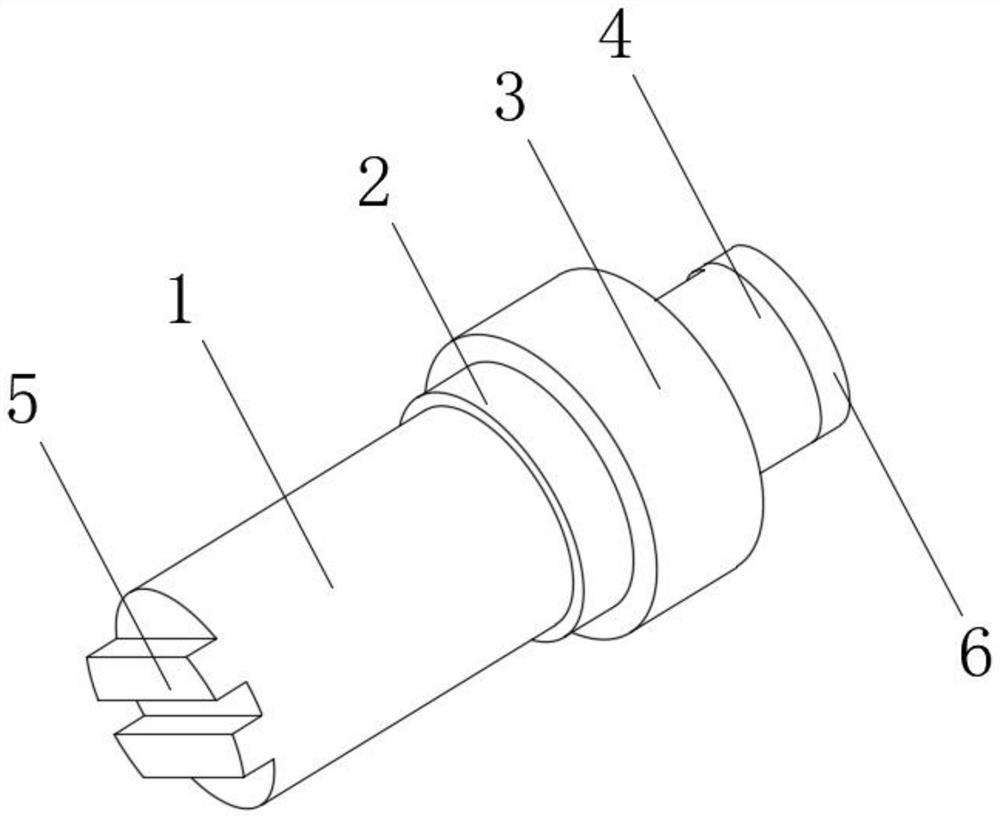
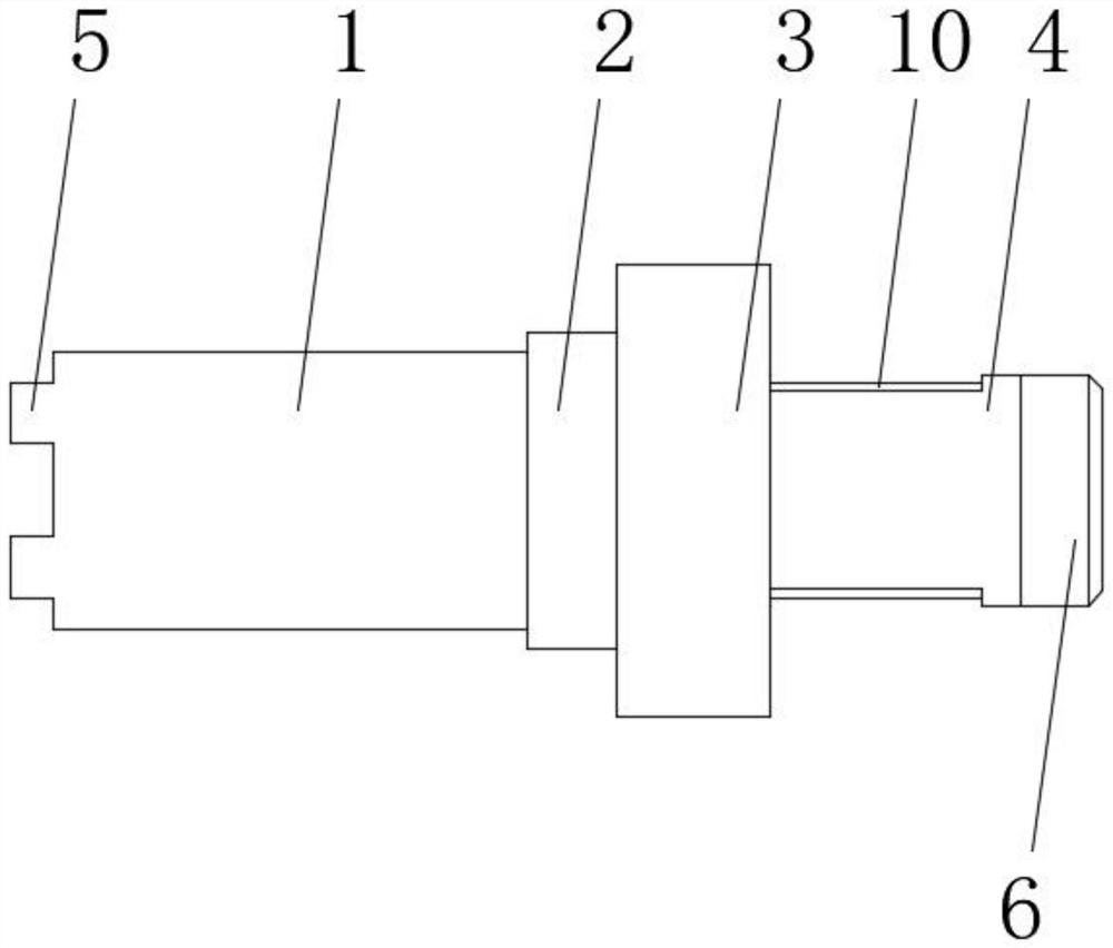
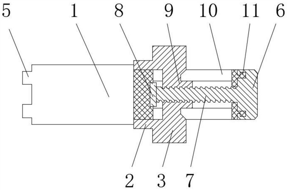
[0022] refer to Figure 1-3 , a crankshaft speed sensor positioning tool, comprising a first tooling step 1, a block 5 is welded to one end of the first tooling step 1, a handle 4 at the other end of the first tooling step 1, and an end of the handle 4 away from the first tooling step 1 An anti-off head 11 is welded;

[0023] The second tooling step 2, the second tooling step 2 is nested on the side surface of the handle 4, and the side of the second tooling step 2 is welded with a limit step 3; and

[0024] Knob 6, the knob 6 is nested on the outside of the anti-off head 11, the inner middle ...


PUM


Abstract

The invention discloses a crankshaft rotating speed sensor positioning tool. Thecrankshaft rotating speed sensor positioning tool comprises: a first tool step, wherein a clamping block is welded to one end of the first tool step, a handle is welded to the other end of the first tool step, and an anti-disengaging head is welded to the end, away from the first tool step, of the handle; a second tool step, wherein the second tool step is embedded in the side surface of the handle, and a limiting step is welded to the side face of the second tool step; and a knob, wherein the knob is nested on the outer side of the anti-disengaging head, wherein a threaded rod is fixedly connected to the middle position of the inner side of the knob. According to the invention, the crankshaft rotating speed sensor positioning tool can quickly and accurately position the mounting position of the crankshaft sensor bracket, so that the crankshaft rotating speed sensor can be smoothly mounted, the working efficiency is improved, the crankshaft rotating speed sensor positioning tool can be matched with different brackets, and the adaptability is improved.

Description

technical field [0001] The invention belongs to the technical field of engine assembly, in particular to a positioning tool for a crankshaft speed sensor. Background technique [0002] The sensor positioning tool currently used is to loosen the crankshaft speed sensor bracket on the gear chamber with two bolts, pass the sensor positioning tool through the sensor installation hole, and the small boss at one end of the tooling is stuck in the upper pointing mark groove of the signal plate , the small boss at the positioning end is easily deformed, and the positioning process is not rigorous. The installation position of the crankshaft speed sensor bracket that is positioned like this is inaccurate, resulting in unreasonable positioning, and finally loses positioning and guiding functions, seriously affecting the production of the engine. Contents of the invention [0003] The purpose of the present invention is to solve the problems in the background technology and provide a...

Claims


Application Information

Patent Timeline
IPC IPC(8): G01P1/00G01P3/00
CPCG01P1/00G01P3/00
Inventor 朱岩
Owner GUANGXI YUCHAI MASCH CO LTD
Why Eureka
Try Eureka