
Device, holographic lens and manufacturing method thereof, and near-to-eye display system

A technology of holographic lens and holographic dry plate, which is applied in the optical field, can solve the problems of inconvenience for users, increase the volume and weight of near-eye display equipment, and achieve the effect of reducing volume and weight

Pending Publication Date: 2021-07-30
SHENZHEN LOCHN OPTICS TECH CO LTD
View PDF4 Cites 4 Cited by
  • Summary
  • Abstract
  • Description
  • Claims
  • Application Information

AI Technical Summary

Problems solved by technology

Near-eye display devices allow users to see the real world while seeing virtual images constructed by computers. Usually, near-eye display devices are limited by optical design and need to be closer to the human eye. People with abnormal vision need to wear near-sighted or hyperopic lenses to see the near-eye display clearly. The display content of the device brings inconvenience to these users
[0003] In the prior art, the waveguide display device is generally embedded in the lens with diopter adjustment to realize the diopter adjustment of the picture in the eyes of the wearer with abnormal vision, or the lens with the degree of vision correction and the waveguide display device are bonded together. Together to achieve vision correction, these solutions all have the problem of increasing the size and weight of near-eye display devices

Method used


Image

  • Device, holographic lens and manufacturing method thereof, and near-to-eye display system
  • Device, holographic lens and manufacturing method thereof, and near-to-eye display system
  • Device, holographic lens and manufacturing method thereof, and near-to-eye display system

Examples


Embodiment Construction

[0034] The present invention will be described in detail below in conjunction with specific embodiments. The following examples will help those skilled in the art to further understand the present invention, but do not limit the present invention in any form. It should be noted that those skilled in the art can make several modifications and improvements without departing from the concept of the present invention. These all belong to the protection scope of the present invention.

[0035] In order to facilitate the understanding of the present application, the present application will be described in more detail below in conjunction with the accompanying drawings and specific embodiments. Unless otherwise defined, all technical and scientific terms used in this specification have the same meaning as commonly understood by one of ordinary skill in the technical field of this application. The terms used in the description of the present application are only for the purpose of ...


PUM


Abstract

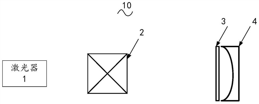
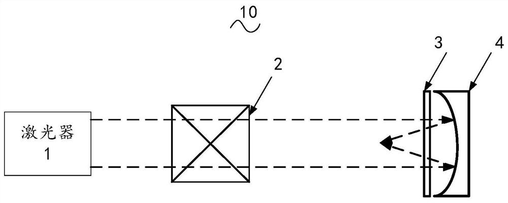
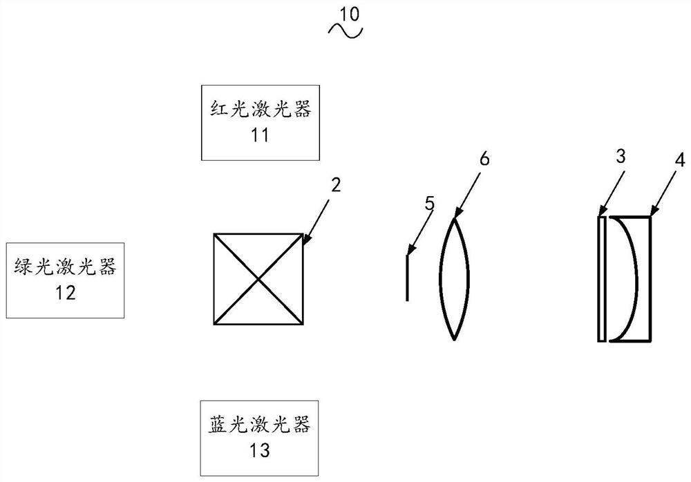
The embodiment of the invention relates to the technical field of optics, in particular to a device for acquiring diopter information, a holographic lens, a manufacturing method of the holographic lens and a near-to-eye display system. The embodiment of the invention provides the device for acquiring diopter information, the holographic lens, the manufacturing method of the holographic lens and the near-to-eye display system. The device comprises at least one laser, and a beam combiner, a holographic dry plate and a refractive mirror which are sequentially arranged along a first light path, wherein the laser is arranged on the incident surface of the beam combiner, the holographic dry plate is arranged on the emergent surface of the beam combiner, and the reflecting surface of the refractive mirror is close to the holographic dry plate. Through the device, the holographic dry plate containing diopter information can be obtained, the holographic dry plate is developed, bleached and fixed to obtain the holographic lens, the holographic lens is applied to a near-eye display system, vision correction of people with abnormal vision can be achieved, and the size and the weight of the near-eye display system are reduced.

Description

technical field [0001] Embodiments of the present invention relate to the field of optical technology, and in particular to a device for acquiring diopter information, a holographic lens and a manufacturing method thereof, and a near-eye display system. Background technique [0002] Augmented reality is a technology that integrates virtual information with the real world, and the near-eye display device is a key link in augmented reality technology. Near-eye display devices allow users to see the real world while seeing virtual images constructed by computers. Usually, near-eye display devices are limited by optical design and need to be closer to the human eye. People with abnormal vision need to wear near-sighted or hyperopic lenses to see the near-eye display clearly. The display content of the device brings inconvenience to these users. [0003] In the prior art, the waveguide display device is generally embedded in the lens with diopter adjustment to realize the diopte...

Claims


Application Information

Patent Timeline
Patent Type & Authority Applications(China)
IPC IPC(8): G02B27/01G03H1/00G02C7/02A61B3/103
CPCG02B27/0172G03H1/0005G02C7/02A61B3/103G02B2027/0174G02B2027/0178G03H2001/0033
Inventor 唐笑运郭晓明宋强马国斌
Owner SHENZHEN LOCHN OPTICS TECH CO LTD
Learn More