Semiautomatic propelling construction mechanism for bridge parapet

A construction device and semi-automatic technology, applied in the direction of bridges, bridge parts, bridge construction, etc., can solve the problems of difficulty in finding, breaking the ring, and taking too much time.

Inactive Publication Date: 2003-12-24
吴光华
View PDF0 Cites 0 Cited by
  • Summary
  • Abstract
  • Description
  • Claims
  • Application Information

AI Technical Summary

Problems solved by technology

[0002] The traditional bridge parapet construction method mainly uses two molds to be fixed on the ground with fixing bolts, and then uses the tie rods for positioning to withstand the pressure of concrete grouting. In order to avoid ring collapse, the formwork must be removed after it is completely solidified. Moreover, due to the positioning of tie rods, holes will be formed on the finished product, and repair work is required, which consumes construction time; in addition, when the construction ground is uneven, the entire line of the completed parapet wall cannot reach the same height and levelness, and must be further detailed What is more serious is that during the fixed construction, it is necessary to drill holes on the construction road surface to set the fixing bolts, so that the pressure of grouting is all borne by the bridge road surface, which will destroy the strength of the bridge deck but is difficult to find, seriously affecting the bridge structure. Desperately in need of improvement
[0003] refer to figure 1 , shows a traditional bridge parapet construction device 6, which mainly uses the track 60 to move the construction device 6 quickly. Before construction, the track 60 must be set on the bridge road surface 70 for the construction device 6 to move. The track 60 must be removed. Obviously, the above-mentioned construction device 6 not only needs to spend a considerable amount of time for setting and removing the track 60, but also destroys the complete road surface 70 that has been laid due to the setting of the track 60; If the counterweight device is installed, it is very easy to cause the construction device 6 to lose its balance and cause tipping, and the construction safety is poor; the construction device 6 does not have a platform space for the construction personnel to check the construction status of the outside or bottom side of the bridge parapet 71, and it is impossible to grasp the other side of the bridge parapet 71 at any time. The construction situation and quality of the side; and the outer formwork 61 of the construction device 6 has no relevant structure to strengthen the positioning, and it is easy to move and relocate when the grouted concrete is under pressure, which will affect the quality of the finished product and construction safety.

Method used


Image

  • Semiautomatic propelling construction mechanism for bridge parapet
  • Semiautomatic propelling construction mechanism for bridge parapet
  • Semiautomatic propelling construction mechanism for bridge parapet

Examples


Embodiment Construction

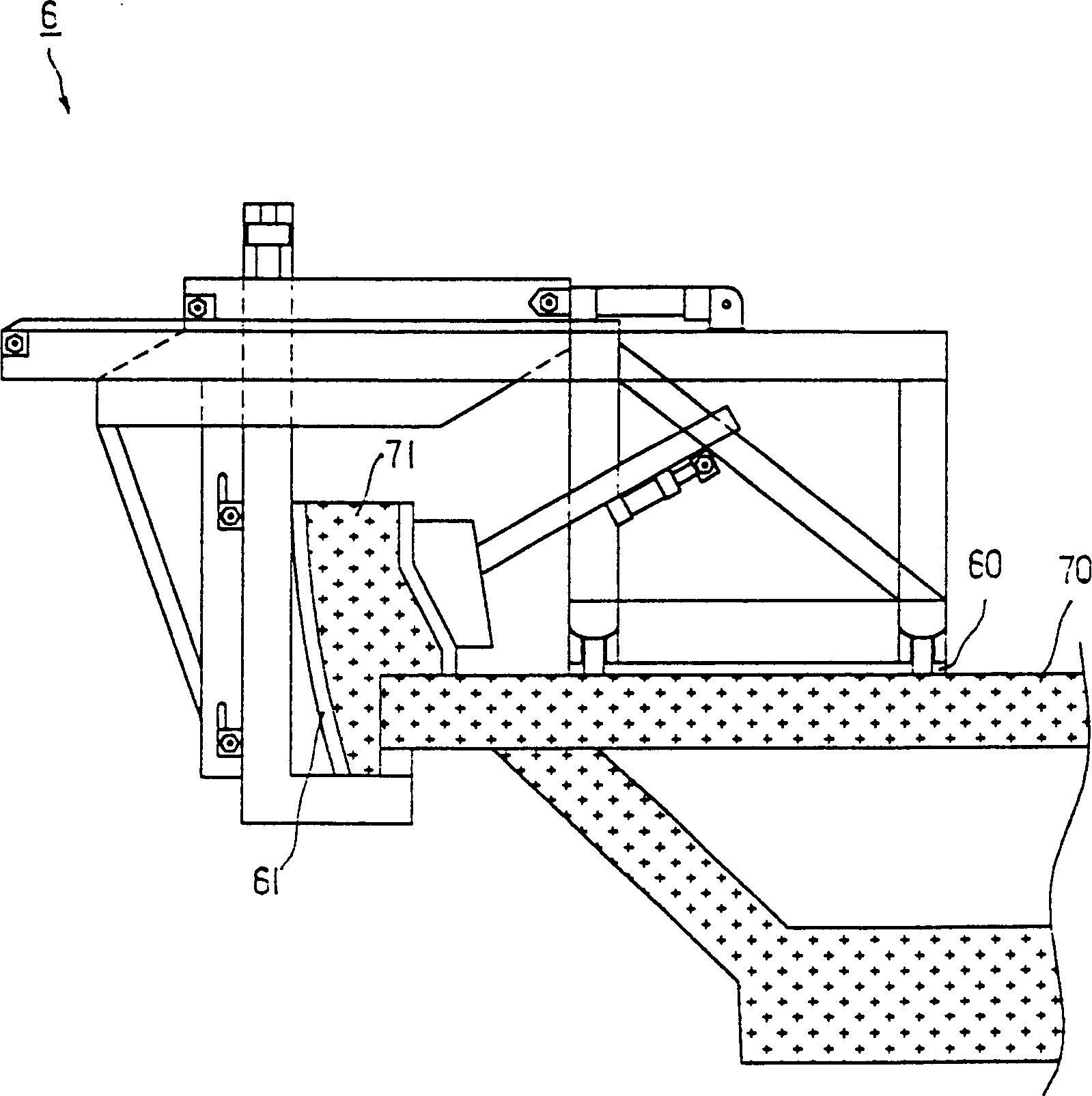
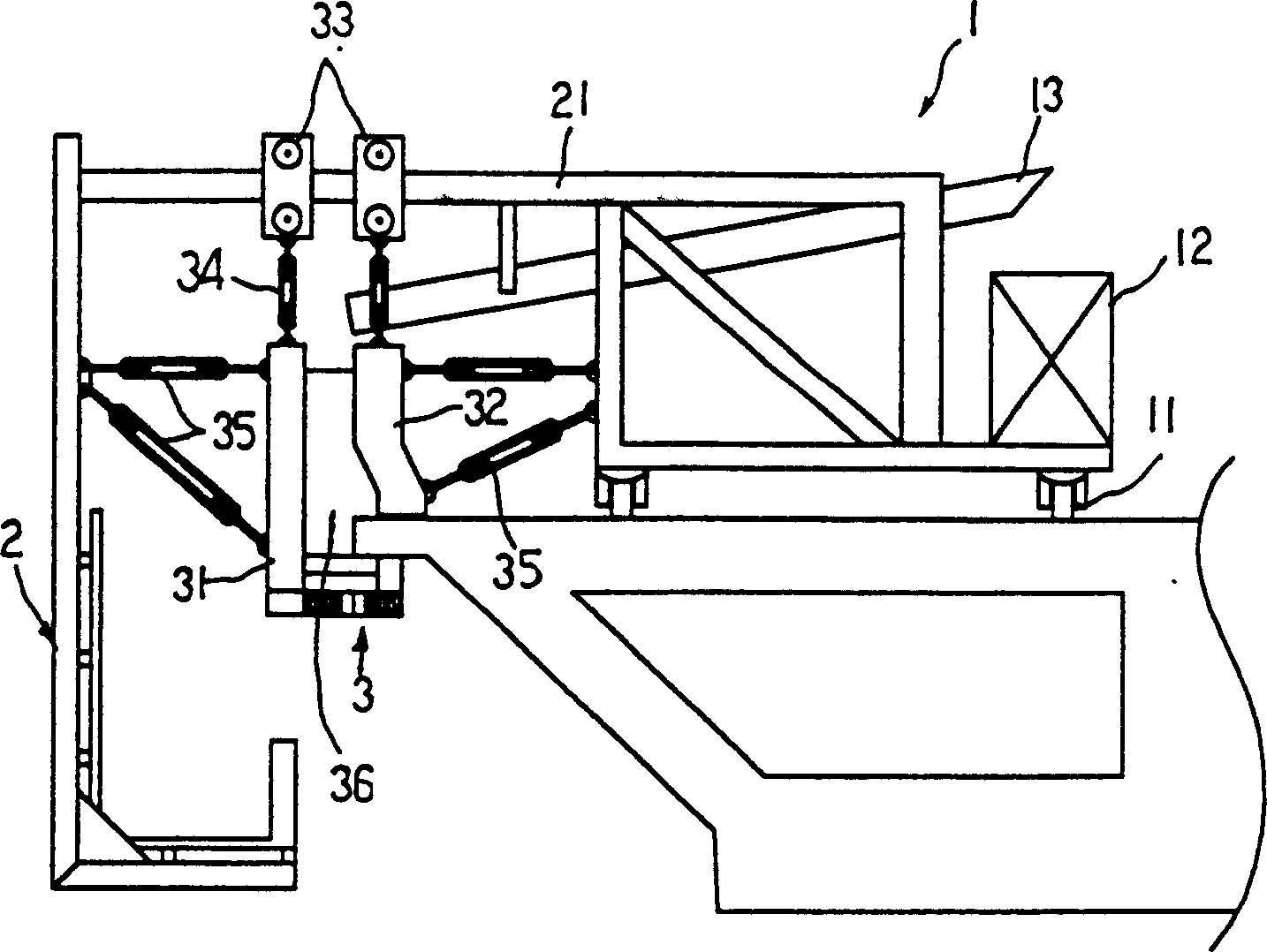
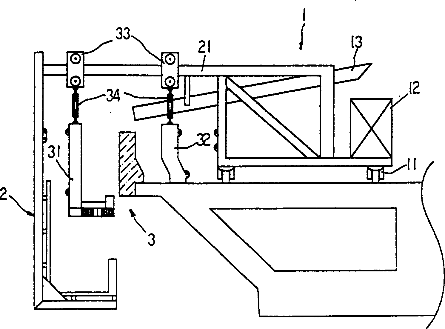
[0014] refer to figure 1 , 2 , bridge parapet semi-automatic propulsion construction device, mainly includes:

[0015] The workbench 1 is a work platform, and a wheel body 11 is arranged at the bottom of the workbench 1, and the wheel body 11 can drive the workbench 1 to move; a counterweight device 12 can be arranged on one side of the workbench 1, thereby avoiding work The platform 1 is overturned during the construction of the parapet of the bridge, which increases the safety of the construction; a beam 21 is extended on the other side of the working platform 1 .

[0016] The construction frame 2 is set on the beam 21 extending from the workbench 1, and can be attached to other components. Its main function is to allow the construction personnel to further inspect the construction situation on the outside or bottom of the bridge parapet, and to grasp the other side of the bridge parapet at any time. The construction situation and quality of the workbench 1 are combined wi...


PUM


Abstract

The present invention aims at raising the construction quality, speed and safety of bridge parapet constructing mechanism. One of the constructino mechanism includes one working bench with wheels at bottom, crossbeam on one side, one construction frame on the crossbeam, inner and outer formworks corresponding to the outer shape of the parapet with the inner and outer formworks being capable of shifting horizontally and with connecting and pressure resisting part in between. The other scheme includes one inverted U-shaped working bench with wheels at bottom, one formworks corresponding the outer shape of the central separating island of bridger road, and the formworks can shift horizontally and have connecting pressure resisting rod. The mechanical of the present invention is used mainly in bridge construction.

Description

Technical field: [0001] The invention relates to special equipment for bridges, in particular to construction equipment for bridge parapets. Background technique: [0002] The traditional bridge parapet construction method mainly uses two molds to be fixed on the ground with fixing bolts, and then uses the tie rods for positioning to withstand the pressure of concrete grouting. In order to avoid ring collapse, the formwork must be removed after it is completely solidified. Moreover, due to the positioning of tie rods, holes will be formed on the finished product, and repair work is required, which consumes construction time; in addition, when the construction ground is uneven, the entire line of the completed parapet wall cannot reach the same height and levelness, and must be further detailed What is more serious is that during the fixed construction, it is necessary to drill holes on the construction road surface to set the fixing bolts, so that the pressure of grouting is...

Claims


Application Information

Patent Timeline
Patent Type & Authority Patents(China)
IPC IPC(8): E01D19/00E01D21/00
Inventor 吴光华
Owner 吴光华
Why Eureka
Try Eureka