
Connector assembly

A connector assembly and connector technology, applied in the direction of connection, connecting parts protective grounding/shielding device, coupling device, etc., can solve the problems of inability to achieve EMC shielding effect, incomplete grounding, long signal return path, etc., to achieve EMC Good shielding, short ground return path, and good crosstalk effect

Active Publication Date: 2021-07-30
SICHUAN HUAFENG ENTERPRISE GRP
View PDF9 Cites 0 Cited by
  • Summary
  • Abstract
  • Description
  • Claims
  • Application Information

AI Technical Summary

Problems solved by technology

[0004] However, this grounding connection method has a long signal return path, and the grounding is not very complete, which cannot achieve a better EMC shielding effect.

Method used


Image

  • Connector assembly
  • Connector assembly
  • Connector assembly

Examples


Embodiment Construction

[0051] In order to make the purpose, technical solutions and advantages of the embodiments of the present invention clearer, the technical solutions in the embodiments of the present invention will be clearly and completely described below in conjunction with the drawings in the embodiments of the present invention. Obviously, the described embodiments It is a part of embodiments of the present invention, but not all embodiments. The components of the embodiments of the invention generally described and illustrated in the figures herein may be arranged and designed in a variety of different configurations.

[0052] Accordingly, the following detailed description of the embodiments of the invention provided in the accompanying drawings is not intended to limit the scope of the claimed invention, but merely represents selected embodiments of the invention. Based on the embodiments of the present invention, all other embodiments obtained by persons of ordinary skill in the art wi...


PUM


Abstract

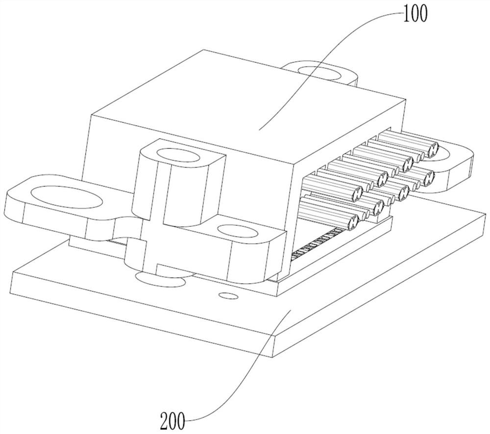
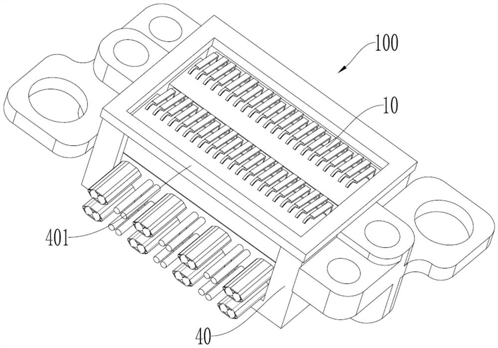
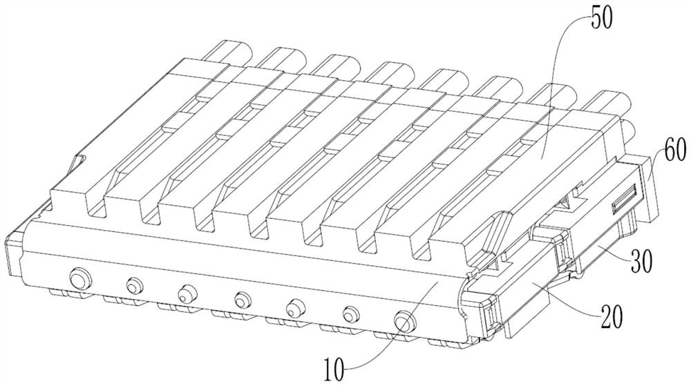
The invention relates to the technical field of connectors, and discloses a connector assembly, comprising: a first connector comprising a housing, a signal transmission assembly partially arranged in the housing, and a first conductive member, the signal transmission assembly comprising a wire, the first conductive member being arranged on a contact surface of the housing, the first conductive member being electrically connected to a ground wire of the wire through the housing; a second connector in butt joint with the first connector, wherein the second connector comprises a connector body and a second conductive member, the second conductive part is arranged on the connector body and electrically connected with the signal ground of the connector body, and when the first connector is in butt joint with the second connector, the first conductive member is connected with the second conductive member so as to conduct the grounding wire and the signal ground. A grounding loop formed by the first conductive member and the second conductive member does not need to pass through a grounding terminal, so that a grounding backflow path is shorter and more complete, the crosstalk effect is better, and EMC shielding is better.

Description

technical field [0001] The present invention relates to the technical field of connectors, in particular to a connector assembly. Background technique [0002] High-speed connectors are connector products with strong transmission capabilities among all connector product types at present, and they are used in various industries. [0003] An existing mini high-speed connector includes two module assemblies, the conductive terminals of the two module assemblies are arranged side by side, and the two module assemblies are stacked up and down and arranged in a misplaced manner. When the high-speed connector is connected to the mating connector (usually a PCB), the grounding terminal of the high-speed connector is connected to the grounding terminal of the mating connector to form a grounding loop. [0004] However, this grounding connection method has a long signal return path, and the grounding is not very complete, which cannot achieve a better EMC shielding effect. [0005] ...

Claims


Application Information

Patent Timeline
IPC IPC(8): H01R13/648H01R12/70
CPCH01R13/648H01R12/70
Inventor 王超刘兴平胡盛王烈
Owner SICHUAN HUAFENG ENTERPRISE GRP
Learn More