
Laser source, laser device and method of cutting tissue

A technology of laser devices and laser sources, which is applied in the field of laser sources and can solve problems such as low efficiency

Pending Publication Date: 2021-07-30
ADVANCED OSTEOTOMY TOOLS - AOT
View PDF15 Cites 1 Cited by
  • Summary
  • Abstract
  • Description
  • Claims
  • Application Information

AI Technical Summary

Problems solved by technology

Even with aqueous spray cooling of the surface, which is known to increase ablation efficiency, adipose tissue is also hydrophobic, and when using a beam wavelength from, for example, the Er:YAG laser emission line of about 3 μm that is strongly absorbed by water, the cutting efficiency, ablation process is still inefficient

Method used


Image

  • Laser source, laser device and method of cutting tissue
  • Laser source, laser device and method of cutting tissue
  • Laser source, laser device and method of cutting tissue

Examples


Embodiment Construction

[0069] In the following description, certain terms are used for convenience and are not intended to limit the present invention. The terms "right", "left", "up", "down", "under" and "above" refer to directions in the drawings. Terminology includes the explicitly mentioned term, its derivatives and terms with similar meanings. In addition, spatially relative terms such as "beneath", "below", "lower", "above", "upper", "proximal ", "distal", etc., can be used to describe the relationship of one element or feature to another element or feature as shown in the figure. These spatially relative terms are intended to encompass different positions and orientations of the device in use or operation in addition to the position and orientation shown in the figures. For example, if the device in the figures is turned over, elements described as "below" or "beneath" other elements or features would then be oriented "above" or "above" the other elements or features. Thus, the exemplary t...


PUM


Abstract

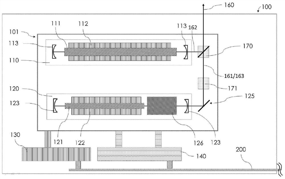
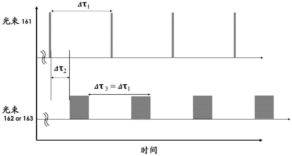
A laser source (101) comprises (i) a first beam generating configuration (111, 112, 113) adapted to generate a pulsed primary ablating laser beam (162) with pulses having a first emission spectrum and a first temporal pulse width to ablate one type of tissue, (ii) a second beam generating configuration (121, 122, 123) adapted to generate a pulsed secondary ablating laser beam (163) with pulses having a second emission spectrum different from the first emission spectrum and a second temporal pulse width to ablate another type of tissue different than the one type of tissue ablated by the primary laser beam (162), (iii) a third beam generating configuration (121, 122, 123, 126) adapted to generate a pulsed analysis laser beam (161) with at least one pulse having a third emission spectrum and a third temporal pulse width shorter than the first temporal pulse width and shorter than the second temporal pulse width, and (iv) a beam directing optics (125) with beam aligning elements adapted to align the primary ablating laser beam, the secondary ablating laser beam (163) and the analysis laser beam (161) such that the laser source (101) propagates the laser beams (160) along a same propagation path.

Description

technical field [0001] The invention relates to a laser source according to the preamble of independent claim 1, and more particularly to a laser device and a method of cutting tissue with such a laser source. Such laser sources configured to propagate multiple laser beams are useful in many applications or fields. Background technique [0002] For cutting and drilling materials in various technical fields, the use of equipment that applies a laser beam to the material is becoming more and more popular. Today, this type of cutting or drilling is common in industrial applications, as it allows efficient and flexible machining of workpieces with high precision. Furthermore, cutting and drilling with lasers is becoming more and more suitable for cutting hard tissues of the human body or animals, such as bones, cartilage, etc. For example, in computer assisted surgery it is known to use a laser beam as a cutting tool. More specifically, for example, in WO 2011 / 035792 A1, a co...

Claims


Application Information

Patent Timeline
Patent Type & Authority Applications(China)
IPC IPC(8): A61B18/20A61B17/00
CPCA61B18/203A61B2017/00172A61B2018/2075A61B2018/20359A61B18/201A61B2018/00565A61B2018/00577A61B2018/00601A61B2018/00904A61B2018/2035
Inventor A·E·布鲁诺K·O·伯恩森M·佩尔R·克尔恩伯格
Owner ADVANCED OSTEOTOMY TOOLS - AOT
Learn More