Steering control device

A steering control and steering torque technology, applied in automatic steering control components, steering mechanisms, steering rods, etc., can solve problems such as large impact and impact sound, and driver discomfort, and achieve the effect of suppressing impact and impact sound.

Active Publication Date: 2021-07-30
NSK LTD
View PDF11 Cites 0 Cited by
  • Summary
  • Abstract
  • Description
  • Claims
  • Application Information

AI Technical Summary

Problems solved by technology

When the end contact occurs at a high steering speed, there may be a large impact and impact sound (squeak) that makes the driver feel uncomfortable

Method used


Image

  • Steering control device
  • Steering control device
  • Steering control device

Examples


no. 1 Embodiment approach

[0041] (structure)

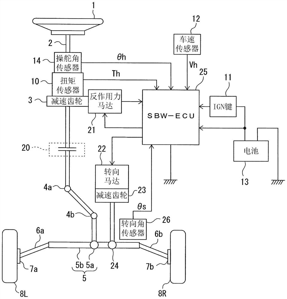
[0042] The present invention is applicable to a steering device that controls the steering angle of a steering mechanism (that is, the steering angle of a steered wheel) according to a target steering angle. figure 1 As an example of such a steering device, a steering device having a steer-by-wire (SBW: Steer By Wire) mechanism that mechanically separates a steering mechanism and a steering mechanism is shown. However, the present invention is not limited to a steering device having a steer-by-wire mechanism, and can be widely applied to various steering devices as long as the steering angle of the steering mechanism is controlled based on a target steering angle.

[0043] The steering shaft (steering shaft, steering wheel shaft) 2 of the steering wheel 1 passes through a reduction gear (worm gear) 3 constituting a reduction mechanism, a backup clutch 20, universal joints 4a and 4b, a rack and pinion mechanism 5, and a steering rod 6a, 6b, and further con...

no. 2 Embodiment approach

[0235] The steering control device according to the second embodiment sets the target angular velocity ωr0 of the angular velocity ω of the first steering angle θs, controls the angular velocity so that the angular velocity ω approaches the target angular velocity ωr0, and performs the same end contact shock mitigation control as described above.

[0236] In the end contact shock mitigation control, as shown in the above formula (3), the steering torque Tm acting in the direction of returning the steering mechanism to the neutral position includes an elastic torque component (K0·θr) and a viscous torque component (μ·ω) .

[0237] The elastic torque (K0·θr) is a component obtained by multiplying the control angle θr by the constant K0, and can be interpreted as a physical quantity having the same unit as the angle.

[0238] On the other hand, the viscous torque (μ·ω) is a component obtained by multiplying the angular velocity ω by a coefficient μ, and can be interpreted as a ph...


PUM


Abstract

A steering control device comprises: a target steering angle computation unit (30) that computes a target steering angle ([theta]sr0) of a steering mechanism on the basis of at least a second steering angle ([theta]h) of the steering mechanism; a steering angle displacement computation unit (31) that, when a third steering angle is within an angle range from the maximum steering angle that the third steering angle can assume to a first threshold value steering angle, the third steering angle being either a first steering angle ([theta]s) or a second steering angle ([theta]h) of the steering mechanism, computes a steering angle displacement ([theta]r) of the third steering angle with reference to the first threshold value steering angle; a steering angle correction value computation unit (32) that computes a steering angle correction value ([delta][theta]) in accordance with at least the steering angle displacement ([theta]r); a steering angle correction value limiting unit (43) that limits the steering angle correction value ([delta][theta]) in accordance with the steering state, the angular velocity ([omega]) of the third steering angle, and the third steering angle; and a correction target steering angle computation unit (33) that corrects the target steering angle ([theta]sr0) using a limited steering angle correction value ([delta][theta]a).

Description

technical field [0001] The present invention relates to steering control devices. Background technique [0002] When the steering angle increases to reach the mechanical maximum rudder angle in the steering mechanism of the vehicle, the rack shaft of the steering mechanism reaches the stroke end and the steering angle cannot be further increased. The state in which the rack shaft reaches the stroke end as described above is called "end contact". When the end contact occurs at a high steering speed, there is a possibility that a large impact and a bump sound (squeak) may be generated to make the driver feel uncomfortable. [0003] Patent Document 1 describes a technique for suppressing an increase in the steering angle near the maximum steering angle in a system (for example, a steer-by-wire system) that controls the steering angle of a steering mechanism based on a target steering angle. [0004] In the technique described in Patent Document 1, a steering reaction force fo...

Claims


Application Information

Patent Timeline
Patent Type & Authority Applications(China)
IPC IPC(8): B62D5/04B62D6/00B62D101/00B62D113/00B62D117/00B62D119/00
CPCB62D5/04B62D6/00B62D5/0469B62D5/0463
Inventor 坂口徹北爪徹也丸山翔也
Owner NSK LTD
Why Eureka
Try Eureka