Skull pelvic ring traction device convenient to operate

A technology of traction device and pelvic ring, applied in the field of medical equipment, can solve problems such as inability to realize head angle rotation, single structure, traction structure protection, etc.

Pending Publication Date: 2021-08-03
王孝宾
View PDF7 Cites 0 Cited by
  • Summary
  • Abstract
  • Description
  • Claims
  • Application Information

AI Technical Summary

Problems solved by technology

[0007] In order to solve the above technical problems, the present invention provides an easy-to-operate skull-pelvic ring traction device to solve the problem that the existing device has a single structure and cannot realize the marking prompt of the traction distance, and the marking structure cannot realize the traction structure at the same time Moreover, the existing device cannot realize quick clamping and adjustment of heads of different sizes; finally, the existing device cannot realize the angle rotation in the process of head traction, and the problem of automatic locking after rotation

Method used


Image

  • Skull pelvic ring traction device convenient to operate
  • Skull pelvic ring traction device convenient to operate
  • Skull pelvic ring traction device convenient to operate

Examples


Embodiment

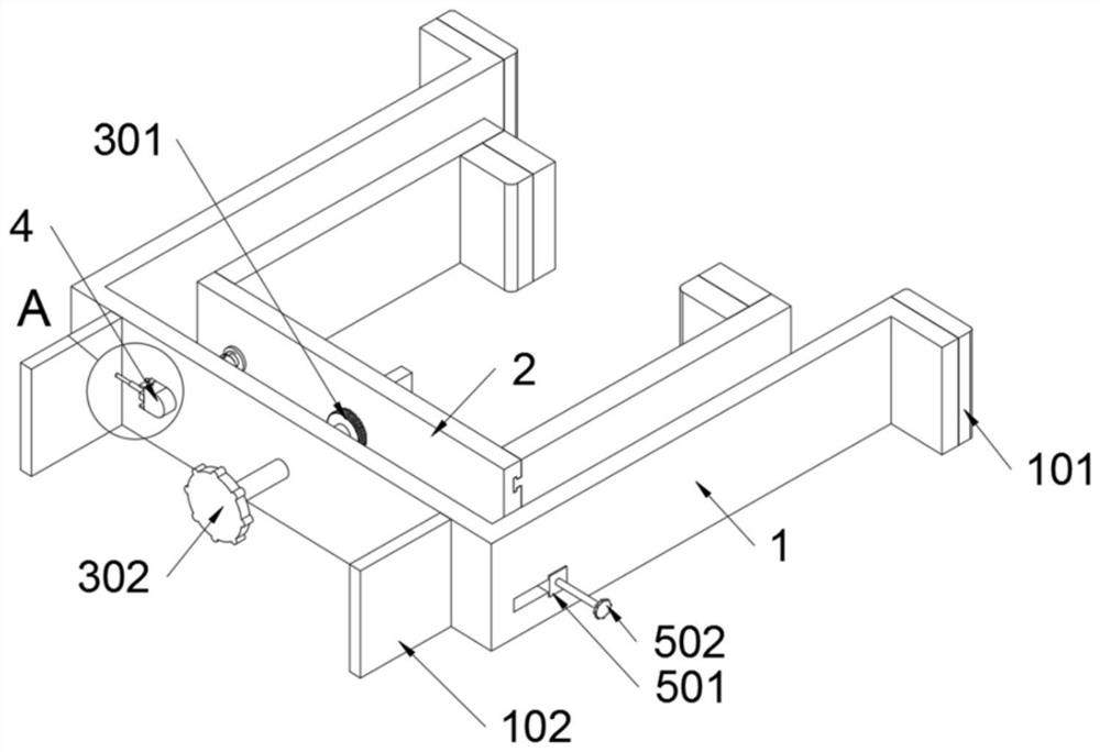
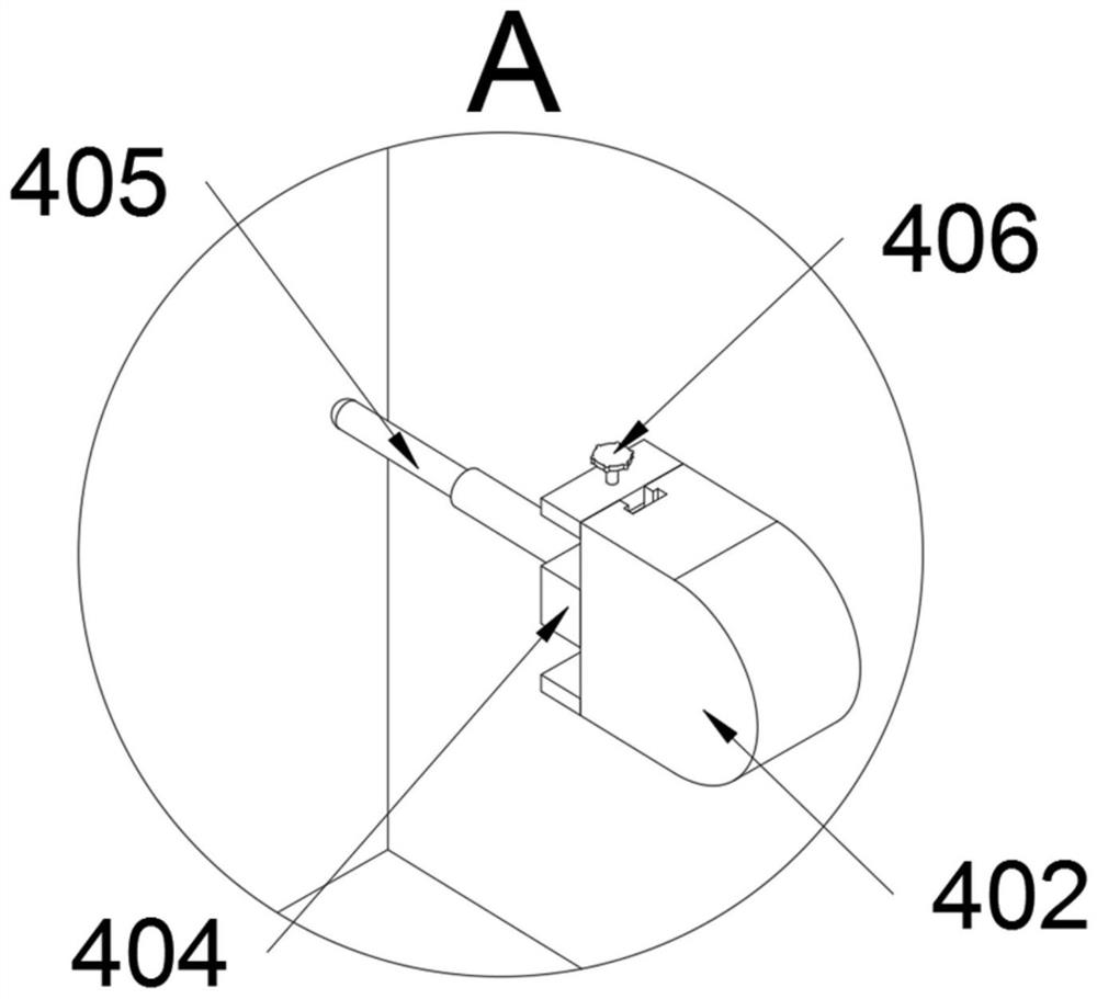
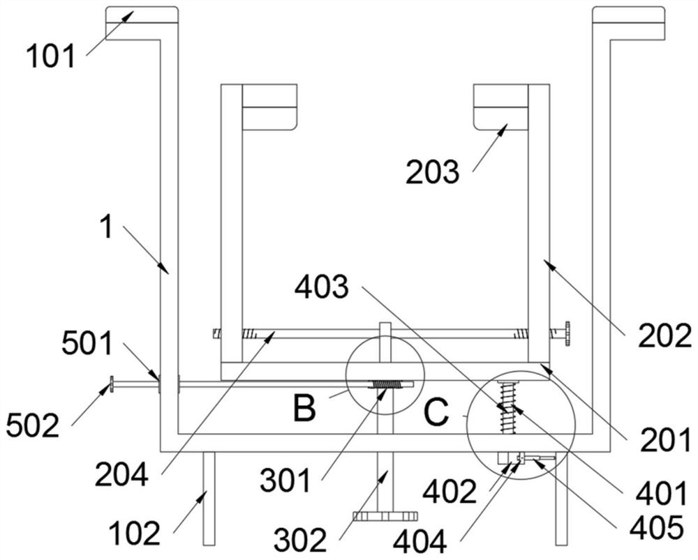
[0034] as attached figure 1 to attach Figure 8 Shown:

[0035] The present invention provides a craniopelvic ring traction device that is easy to operate, including a first frame body 1 and a protective block 102; a tensile structure 3 is installed on the first frame body 1, and a clamping structure 2 is installed on the tensile structure 3; Marking structure 4 is installed on a frame body 1, and adjustment structure 5 is also installed on the first frame body 1; Refer to as image 3 , the protective block 102 is a rectangular block structure, and the height of the protective block 102 is 15cm; when the bottom end faces of the two protective blocks 102 are in contact with the ground, the tail end of the threaded rod A302 is not in contact with the ground, and the two protective blocks 102 are in common The protective structure of the tensile structure 3 is formed, thereby preventing the tensile structure 3 from being damaged when the tail end of the threaded rod A302 touche...


PUM


Abstract

The invention provides a skull pelvic ring traction device convenient to operate, relates to the technical field of medical apparatuses and instruments, and solves the problems that marking prompt of a traction distance cannot be realized, and a marking structure cannot realize protection of a traction structure at the same time; the rapid clamping adjustment of the skull with different sizes cannot be realized; the problems that angle rotation in the head traction process and automatic locking after rotation cannot be achieved in the prior art are solved. A head pelvic ring traction device convenient to operate comprises a first frame body and a protection block. A stretching structure is installed on the first frame body, and a clamping structure is installed on the stretching structure. Due to the fact that the height of the protection blocks is 15 cm, when the bottom end faces of the two protection blocks make contact with the ground, the tail end of the threaded rod A does not make contact with the ground, the two protection blocks jointly form a protection structure of the stretching structure, and therefore the situation that the tail end of the threaded rod A makes contact with the ground to cause damage to the stretching structure when falling off accidentally can be prevented.

Description

technical field [0001] The invention belongs to the technical field of medical instruments, and more specifically relates to a traction device for a craniopelvic ring that is easy to operate. Background technique [0002] Traction with a traction device is required after head and neck injuries. [0003] For example, the application number: CN201510179763.1, the present invention relates to a traction device for the central part of the dog's face, including a traction frame and a traction belt for pulling the central part of the dog's facial bone; the shape of the traction frame is a "U" shape corresponding to the shape of the dog's skull Frame body, skull fixation screws fix the traction frame on the dog’s skull on both sides of the dog’s skull; a traction shaft is installed at the connecting end of the “U”-shaped frame body, when the traction frame is fixed on the dog’s skull, the traction shaft is The vertical direction is located in front of the dog's face; a traction cr...

Claims


Application Information

Patent Timeline
Patent Type & Authority Applications(China)
IPC IPC(8): A61D1/00
CPCA61D1/00
Inventor 王孝宾胡佳
Owner 王孝宾
Why Eureka
Try Eureka