Mouth gag for rehabilitation exercise after oral cancer radiotherapy

A technology of oral cancer and mouth opener, which is applied in oral mirrors, applications, gymnastics equipment, etc., and can solve the problems of patients' discomfort, placement in the mouth, and inconvenient handling of saliva

Inactive Publication Date: 2021-08-03
CHONGQING UNIV CANCER HOSPITAL
View PDF5 Cites 0 Cited by
  • Summary
  • Abstract
  • Description
  • Claims
  • Application Information

AI Technical Summary

Benefits of technology

This technology helps reduce swallowing through an improved way for patients with breathing problems due to excessive saltiness during their treatment process. It uses special shapes made of materials like springs instead of traditional metal plates to allow airflow while keeping them closed tightly around themselves. Additionally, there are guiding mechanisms on top to help remove any residue left behind after each use. Overall, this innovation makes dentistry more effective at reducing discomfort caused by acid reflux disease (AR).

Problems solved by technology

The technical problem addressed in this patented text relates to improving dentistry practices during radiation therapies such as orthodontic treatment that involve closing off certain parts of the teeth called temporoarsusceptive (TSO) jaw bone. This issue arises because current methods require patients' own hands to open their mouth while carrying out these treatments, making them hard to handle without disrupting other areas around they.

Method used


Image

  • Mouth gag for rehabilitation exercise after oral cancer radiotherapy
  • Mouth gag for rehabilitation exercise after oral cancer radiotherapy
  • Mouth gag for rehabilitation exercise after oral cancer radiotherapy

Examples


Embodiment 1

[0028] Example 1: Please refer to Figure 1-Figure 6 , the specific embodiments of the present invention are as follows:

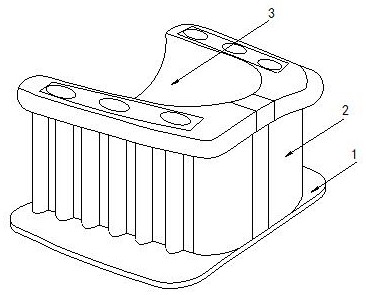
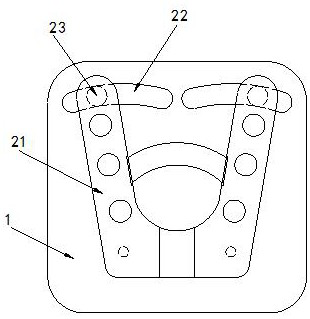
[0029] Its structure includes a base 1, a main body 2, and a movable groove 3. The upper end of the base 1 is provided with a main body 2. The main body 2 is U-shaped. The movable groove 3 is located inside the main body 2. The main body 2 includes a movable device 21. Sliding groove 22, sliding block 23, the movable device 21 is engaged on the upper end of the base 1, two sliding grooves 22 are provided, and are respectively located on the upper end surface of the base 1, and the sliding block 23 is embedded in the The bottom rear end of the movable device 21 is engaged with the sliding groove 22 .

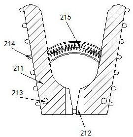
[0030] The movable device 21 includes a swing block 211, a rubber block 212, a rotating shaft 213, a friction block 214, and a return spring 215. The front ends of the two movable devices 21 are connected, the rotating shafts 213 are provided with two, and ...

Embodiment 2

[0035] Example 2: Please refer to Figure 7-Figure 9 , the specific embodiments of the present invention are as follows:

[0036]The suction head a12 includes a protective pad c1, an air suction groove c2, a through hole c3, and a guide c4, the protective pad c1 is embedded in the upper end of the suction head a12, and the suction groove c2 is arranged inside the suction head a12 , there are more than five through holes c3 arranged around the outer end of the suction groove c2, more than eight guide devices c4 are arranged inside the through holes c3, and the guide devices c4 is V-shaped, which is beneficial to block the sucked saliva through the guiding device c4.

[0037] The guide device c4 includes a guide plate c41, an air hole c42, and an attachment hole c43. The guide plate c41 is embedded in the end face of the suction groove c2, and the air flow hole c42 is arranged on the top side of the guide plate c41. There are more than eight attachment holes c43, and they are ...


PUM


Abstract

The invention discloses a mouth gag for rehabilitation exercise after oral cancer radiotherapy. The mouth gag structurally comprises a base, a main body and a movable groove; the upper end of the base is provided with the main body, the main body is U-shaped, and the movable groove is located in the inner side of the main body; the main body comprises a movable device, a sliding groove and a sliding block; the movable device comprises a swing block, a rubber block, a rotating shaft, a friction block and a reset spring; the swing block comprises an adsorption groove, a rubber ring, a spring plate, an elastic piece and a vent hole; the adsorption groove comprises a cover plate, a suction head and a liquid collection box; and the liquid collection box comprises a liquid inlet, a liquid baffle, a discharging opening and a cleaning opening. The reset spring is utilized to reduce the extrusion pressure on the spring plate, the elastic piece can push the spring plate to drive the rubber ring to open, and the rubber ring can suck air outwards through the vent hole, so that saliva in the oral cavity is sucked into an adsorption groove, and the patient can be assisted in cleaning the saliva generated in the oral cavity during exercise.

Description


Claims


Application Information

Patent Timeline
Owner CHONGQING UNIV CANCER HOSPITAL
Why Eureka
Try Eureka