
Novel double-fluid dry fog dust suppression device

A two-fluid, dry mist technology, applied in liquid spraying devices, spraying devices, using liquid separating agents, etc., can solve the problems of unfavorable flexibility, unfavorable spray fluency of the device, fineness of dry mist particles, and the device cannot be moved and used, etc. Achieve the effect of increasing the spray area, increasing the scope of use, and improving the dust suppression effect.

Pending Publication Date: 2021-08-03
JINAN KAILITE ENVIRONMENTAL PROTECTION EQUIP CO LTD
View PDF0 Cites 0 Cited by
  • Summary
  • Abstract
  • Description
  • Claims
  • Application Information

AI Technical Summary

Problems solved by technology

[0003] However, the dual-fluid dry fog dust suppression devices currently on the market can only spray at one angle, which is not conducive to the spray area of ​​the device, resulting in low dust suppression effect. Generally, the spray direction cannot be adjusted from multiple angles, which is not conducive to the flexibility of use. Adjust and use according to the situation. Generally, the device is installed in a fixed position, and the device cannot be moved for use, which is not conducive to the scope of use. Most of the spray is carried out through a group of air inlet and outlet pipes, and multiple groups of nozzles are shared, resulting in low air pressure and water pressure, which is not conducive to the device. Excellent spray fluency and fineness of dry fog particles

Method used


Image

  • Novel double-fluid dry fog dust suppression device
  • Novel double-fluid dry fog dust suppression device
  • Novel double-fluid dry fog dust suppression device

Examples


Embodiment Construction

[0024] The following will clearly and completely describe the technical solutions in the embodiments of the present invention with reference to the accompanying drawings in the embodiments of the present invention. Obviously, the described embodiments are only some, not all, embodiments of the present invention. Based on the embodiments of the present invention, all other embodiments obtained by persons of ordinary skill in the art without making creative efforts belong to the protection scope of the present invention.

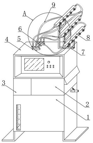
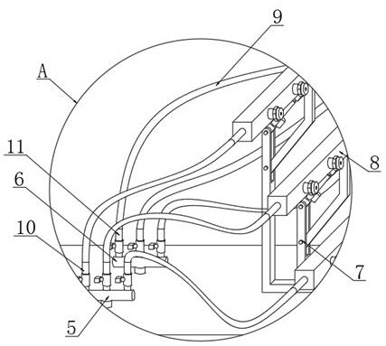
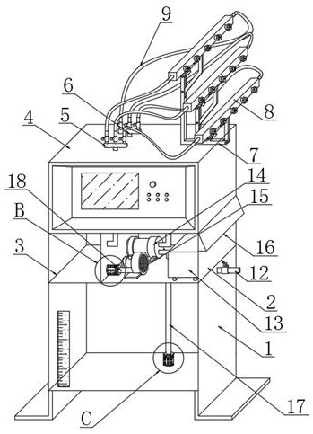
[0025] see Figure 1-7 , in the embodiment of the present invention, a novel dual-fluid dry fog dust suppression device includes a water tank 1, the upper surface of the water tank 1 is equipped with a working cabinet 2 and a high-pressure gas tank 3, and the upper surface of the working cabinet 2 is equipped with a control box 4, A water outlet pipe 5 and an air outlet pipe 6 are installed on the upper surface of the control box 4, and a support frame 7 is fi...


PUM


Abstract

The invention relates to the technical field of dry fog dust suppression, in particular to a novel double-fluid dry fog dust suppression device which comprises a water tank, a work doing machine box and a high-pressure air box are installed on the upper surface of the water tank, a control box is installed on the upper surface of the work doing machine box, and a water outlet pipe and an air outlet pipe are installed on the upper surface of the control box. A supporting frame is fixed to one side of the upper surface of the control box, three atomization components are installed on the supporting frame, gas-liquid hoses are installed at the two ends of each atomization component in a penetrating mode, a water adding opening is welded to the upper end of the outer surface of one side of the water tank in a penetrating mode, and a diesel generator, a water pump and an air pump are installed in the acting machine box. The three sets of spraying structures are arranged, the spraying angles of the three sets of spraying structures can be independently adjusted, the independent power supply structure and the independent water tank are arranged and can be movably used, the three sets of air inlet and outlet pipes are provided with independent air-liquid outlets, air and liquid can be filtered, and the atomization nozzles are prevented from being blocked.

Description

technical field [0001] The invention relates to the technical field of dry fog and dust suppression, in particular to a novel dual-fluid dry fog and dust suppression device. Background technique [0002] Dry fog dust suppression is an advanced technology that is superior to the traditional spray dust removal technology. It has been widely used in mines, power plants, ports, garbage disposal stations and other places. To capture dust, let the water mist combine with the dust particles in the air to form agglomerates of dust and water mist, which will settle down under the action of gravity to achieve source dust suppression. [0003] However, the dual-fluid dry fog dust suppression devices currently on the market can only spray at one angle, which is not conducive to the spray area of ​​the device, resulting in low dust suppression effect. Generally, the spray direction cannot be adjusted from multiple angles, which is not conducive to the flexibility of use. Adjust and use ...

Claims


Application Information

Patent Timeline
IPC IPC(8): B01D47/06B05B7/08B05B7/26B05B13/04
CPCB01D47/06B05B7/0876B05B7/0884B05B7/267B05B13/04B05B7/2486
Inventor 张孝堃
Owner JINAN KAILITE ENVIRONMENTAL PROTECTION EQUIP CO LTD
Learn More