Outer rough surface uniform grinding mechanism for steel preparation

A grinding mechanism and rough surface technology, applied in machine tools suitable for grinding workpiece planes, parts of grinding machine tools, and grinding machines, etc., can solve problems such as uneven force on steel, large grinding force on steel, and pits on the outer surface. , to avoid grinding vibration, enhance blocking force, and prevent gaps

Pending Publication Date: 2021-08-03
陈丽娜
View PDF8 Cites 0 Cited by
  • Summary
  • Abstract
  • Description
  • Claims
  • Application Information

AI Technical Summary

Problems solved by technology

[0003] However, the gap in the limit sliding process of the rectangular steel is easy to make the steel move, and the steel is easy to vibrate under the force of grinding and polishing, resulting in inclination, so that the grinding and polishing will easily generate a large grinding force on the steel, causing the steel to be stressed unevenly. Therefore, the outer surface is prone to potholes

Method used


Image

  • Outer rough surface uniform grinding mechanism for steel preparation
  • Outer rough surface uniform grinding mechanism for steel preparation
  • Outer rough surface uniform grinding mechanism for steel preparation

Examples


Embodiment 1

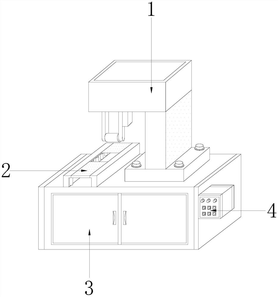
[0026] Such as Figure 1-Figure 5 Shown:

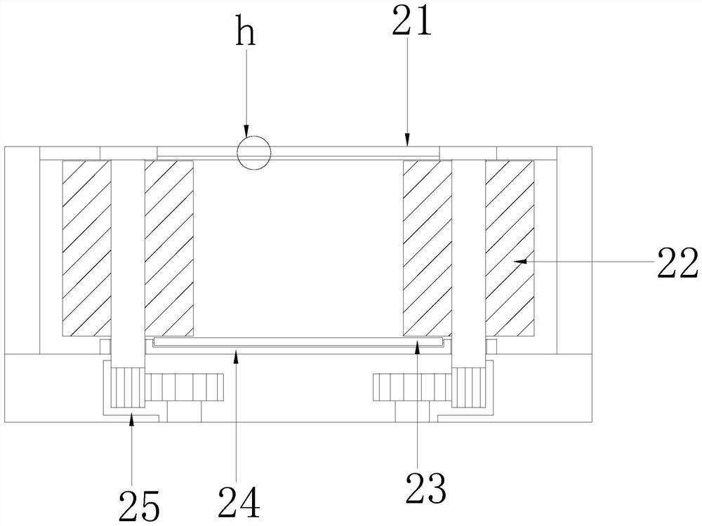
[0027] The present invention is a mechanism for uniformly polishing the surface rough surface for steel preparation, and its structure includes a polisher 1, a polishing fixture 2, a mechanical box 3, and a controller 4. The lower end of the polisher 1 is installed on the upper end of the mechanical box 3, and the control The device 4 is embedded and fixed on the right side of the mechanical box 3, and the lower end of the grinding and fixing device 2 is welded on the upper surface of the mechanical box 3. The grinding and fixing device 2 is provided with a blocking mechanism 21, a rotating mechanism 22, a drum 23, a fixing plate 24, parts Plate 25, the lower end of the blocking mechanism 21 is embedded in the middle of the upper ends of the two part plates 25, the inner lower end of the part plate 25 and the lower ends of the two rotating mechanisms 22 are mutually installed, and the left and right sides of the roller 23 are fixed in...

Embodiment 2

[0034] Such as Figure 6-Figure 8 Shown:

[0035] Wherein, the blocking mechanism 21 is provided with a blocking plate 211, a compression plate 212, and a sliding structure 213, the compression plate 212 is engaged inside the blocking plate 211, and the left and right sides of the sliding structure 213 are installed inside the side of the support plate 214, The support plate 214 is attached to the lower end of the blocking plate 211, and the blocking plate 211 is embedded in the middle of the upper end of the component plate 25. The compression plate 212 is made of rubber material and has a continuous bending structure. The lower end of the supporting plate 214 is a continuous The arc-shaped structure has the effect of less friction points, so that when the steel is polished, the upper surface of the steel slides with the sliding structure 213 on the side of the support plate 214, so that the steel exerts a force on the support plate 214 under the force of grinding and polishi...


PUM


Abstract

The invention discloses an outer rough surface uniform grinding mechanism for steel preparation. The outer rough surface uniform grinding mechanism structurally comprises a polisher, a grinding fixing device, a mechanical box and a controller; the lower end of the polisher is installed at the upper end of the mechanical box, the controller is fixedly embedded in the right side of the mechanical box, the lower end of the grinding fixing device is welded to the upper surface of the mechanical box, and steel slides on a roller on the surface of a fixing plate; meanwhile, the steel is fixed under blocking of a blocking mechanism, a stress plate moves in the direction of an extrusion block, and a friction plate generates a segment structure under friction blocking of a friction block, so that the friction resistance to the side face of the steel is increased, the conditions that the steel deviates during grinding and polishing of the steel and a sliding structure on the upper surface of the steel and the side face of a supporting plate slides are prevented, vibration inclination force is prevented from being generated during grinding and polishing of the steel, gaps are prevented from being generated during steel moving and polishing, steel grinding vibration is avoided, therefore, the acting force on the steel is blocked under the elastic force of rubber balls, and deviation caused by the gaps generated in the steel moving and polishing process is prevented.

Description

technical field [0001] The invention relates to the technical field of steel preparation, in particular to a mechanism for uniformly grinding outer rough surfaces for steel preparation. Background technique [0002] The steel needs to be polished and polished during the processing process. The rectangular steel is fixed to make it slide on the upper limit of the fixed track, so that the grinding mechanism can be controlled to polish the steel, so that the density of the outer surface of the steel becomes larger, and the impact of rust on the steel is reduced. The effect of steel maintenance. [0003] However, the gap in the limit sliding process of the rectangular steel is easy to make the steel move, and the steel is easy to vibrate under the force of grinding and polishing, resulting in inclination, so that the grinding and polishing will easily generate a large grinding force on the steel, causing the steel to be stressed unevenly. Thereby, pits are prone to occur on the...

Claims


Application Information

Patent Timeline
Patent Type & Authority Applications(China)
IPC IPC(8): B24B7/06B24B7/10B24B41/00B24B41/06B24B27/00B24B27/02B24B55/00
CPCB24B7/06B24B7/10B24B41/007B24B41/06B24B27/0015B24B27/02B24B55/00
Inventor 陈丽娜
Owner 陈丽娜
Why Eureka
Try Eureka