Bidirectional interaction projector with reversing function
A projector and functional technology, applied in the field of projectors, can solve problems such as poor teaching effect, poor projector interaction effect, complex structure, etc., and achieve good use effect and excellent heat dissipation effect
- Summary
- Abstract
- Description
- Claims
- Application Information
AI Technical Summary
Problems solved by technology
Method used
Image
Examples
Embodiment 1
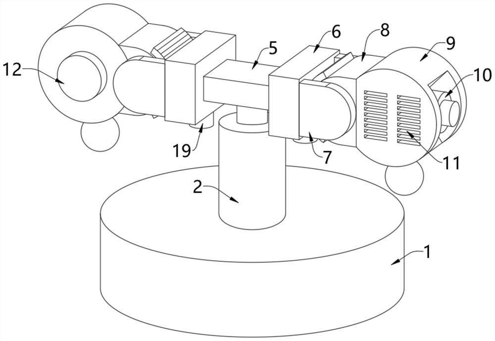
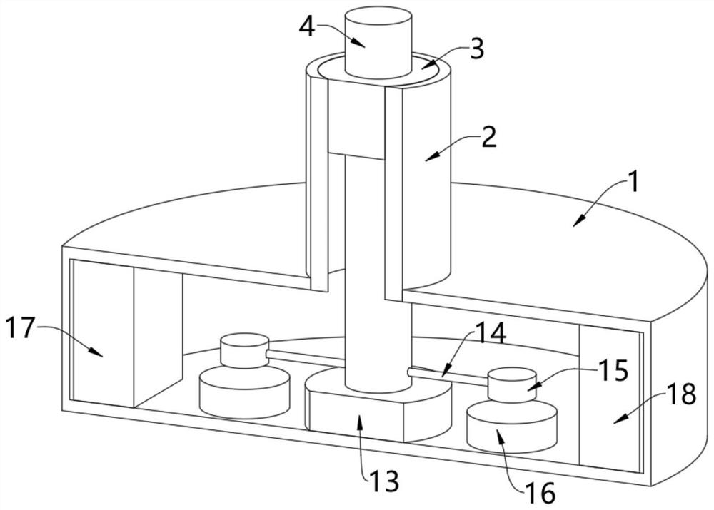
[0045] see figure 1 and figure 2 , a two-way interactive projector with a reversing function, comprising a base 1, a vertical cylinder 2 is fixedly installed at the center of the top of the base 1, a fixed bearing 3 is fixedly installed on the inner wall of the vertical cylinder 2, and a fixed bearing 3 is fixedly installed on the inner wall of the fixed bearing 3 The rotating shaft 4, the top of the rotating shaft 4 is fixedly equipped with a connecting plate 5, and the two ends of the connecting plate 5 are respectively provided with a first projection device and a second projection device, the first projection device and the second projection device all include a fixed plate 6, Side ear 7, rotating column 8, outer cylinder 9 and projector 10, both projectors 10 can project pictures, in actual use, two projectors 10 can project different pictures respectively, and the use effect is better;
[0046] The fixed plate 6 is fixedly mounted on the end of the connecting plate 5, ...
Embodiment 2
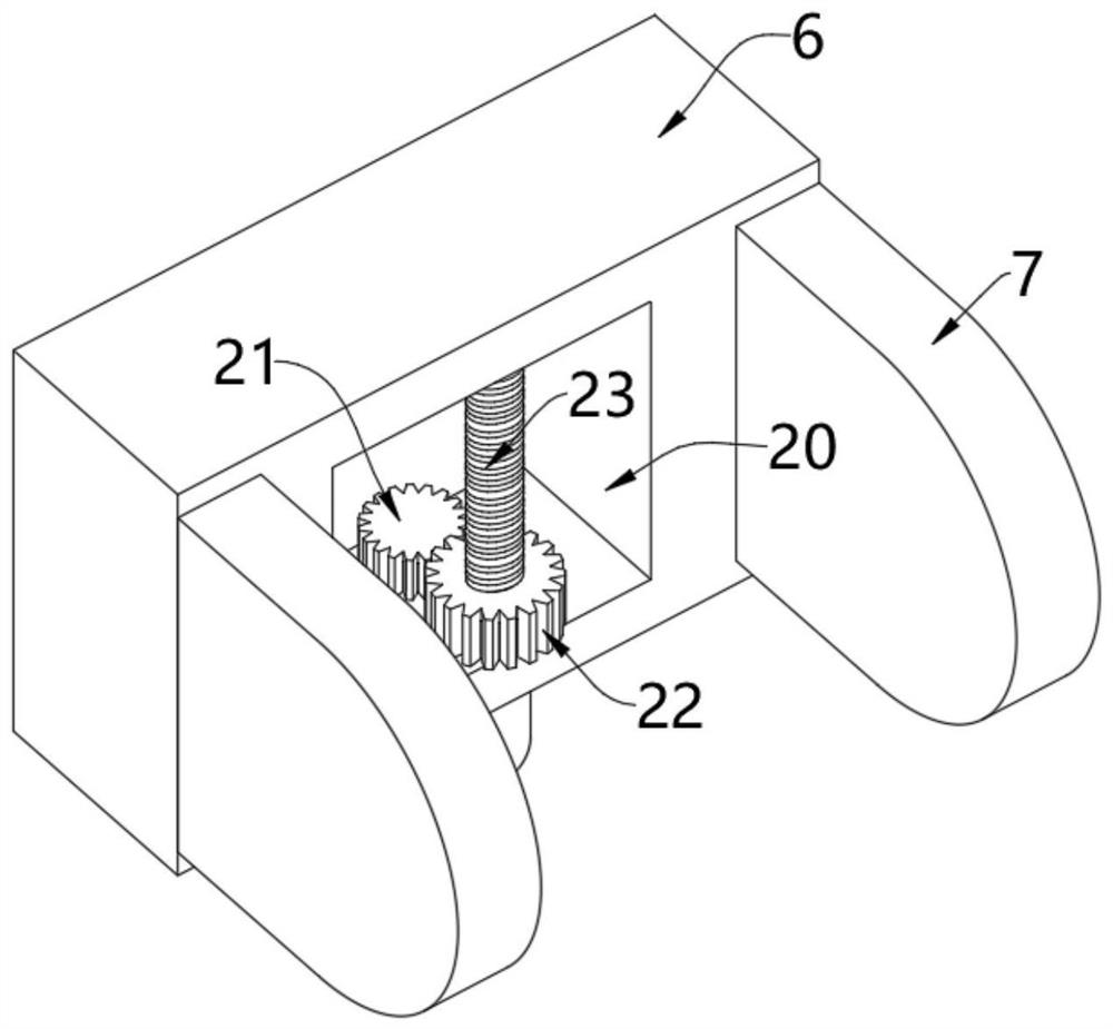
[0054] see image 3 and Figure 4 , on the basis of Embodiment 1, a motor 19 is fixedly installed on the bottom of the fixed plate 6, and a driving wheel 21 is fixedly installed on the top of the output shaft of the motor 19, and the driving wheel 21 is movably arranged inside the cavity 20, and the cavity 20 is opened in Inside the fixed plate 6, the outer wall of the driving wheel 21 is meshed with a driven wheel 22, and the center of the driven wheel 22 is fixedly equipped with a worm 23, and the two ends of the worm 23 are rotated on the inner wall of the cavity 20, and the rotating column 8 is rotated. Between the two side ears 7, an arc-shaped drive plate 24 is fixedly installed on the outer wall of the rotating column 8. The outer wall of the arc-shaped drive plate 24 is formed with worm gear teeth, and the worm screw 23 is meshed with the worm gear teeth. The motor 19 runs to drive its output shaft. The driving wheel 21 at the top rotates, the driving wheel 21 rotates...
Embodiment 3
[0057] see Figure 5 and Image 6 , on the basis of Embodiment 1 and Embodiment 2, central shafts 26 are fixedly installed on the front and rear sides of the outer wall of the projector 10, and the ends of the two central shafts 26 are rotatably arranged on the inner wall of the outer cylinder 9, through which the two central shafts 26 restricts the position of the projector 10 so that the projector 10 can rotate in the outer cylinder 9;
[0058] The projector 10 has a projection head, the end of the projection head extends to the outside of the outer cylinder 9, and the outer wall of the outer cylinder 9 is provided with a projection groove 25 matched with the projection head, and the projection head protrudes through the projection groove 25, which is convenient to be placed on the screen. projection screen;
[0059] The top of the projector 10 is fixedly equipped with a swing rod 27, the top of the swing rod 27 is formed with an arc coupled with the inner wall of the oute...
PUM
 Abstract
Description
Claims
Application Information
 - R&D
- Intellectual Property
- Life Sciences
- Materials
- Tech Scout
- Unparalleled Data Quality
- Higher Quality Content
- 60% Fewer Hallucinations
Browse by: Latest US Patents, China's latest patents, Technical Efficacy Thesaurus, Application Domain, Technology Topic, Popular Technical Reports.
© 2025 PatSnap. All rights reserved.Legal|Privacy policy|Modern Slavery Act Transparency Statement|Sitemap|About US| Contact US: help@patsnap.com


