
Power transmission equipment on-line monitoring system and method

A technology of power transmission equipment and monitoring system, which is applied in general control system, control/regulation system, measuring power, etc. It can solve problems such as limited battery power, limited application of mains power, and impact on sustainable power supply of equipment, achieving a high degree of automation, Avoid insufficient power supply and achieve the effect of continuous power supply

Pending Publication Date: 2021-08-03
NANJING ZHENGTU INFORMATION TECH CO LTD
View PDF6 Cites 0 Cited by
  • Summary
  • Abstract
  • Description
  • Claims
  • Application Information

AI Technical Summary

Problems solved by technology

A large amount of manpower and material resources, due to the environmental impact of the high-voltage transmission line itself and cost constraints, the application of mains power is limited, so the problem of continuous and reliable power supply of the online monitoring equipment itself has not been very properly resolved.
[0003] The traditional on-line monitoring system of power transmission equipment, due to the limited power of its own battery in actual use, in the case of insufficient power supply due to bad weather, it is generally necessary to configure an energy storage battery as a supplementary power supply to achieve continuous power supply to the load , but the charge and discharge times of the energy storage battery are limited. Generally, they will be equipped with new energy power generation devices, including wind power generation and solar power generation. Wind power generation will hinder power generation work in ice-covered weather, and solar power generation in this ice-covered weather will also be received. Limitation, which affects the sustainable power supply of the equipment

Method used


Image

  • Power transmission equipment on-line monitoring system and method
  • Power transmission equipment on-line monitoring system and method
  • Power transmission equipment on-line monitoring system and method

Examples


Embodiment Construction

[0023] The following will clearly and completely describe the technical solutions in the embodiments of the present invention with reference to the accompanying drawings in the embodiments of the present invention. Obviously, the described embodiments are only some, not all, embodiments of the present invention. Based on the embodiments of the present invention, all other embodiments obtained by persons of ordinary skill in the art without making creative efforts belong to the protection scope of the present invention.

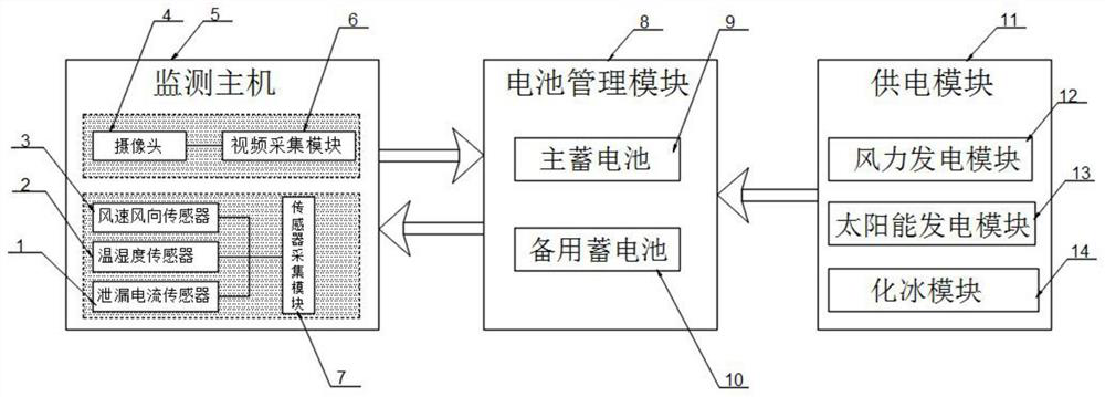
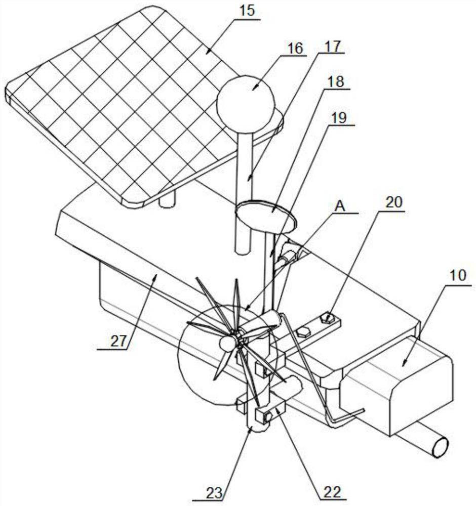
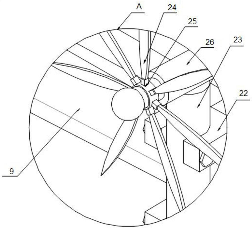
[0024] The present invention provides such figure 1 , 2 and image 3 Among them, including a monitoring host 5, a battery management module 8 and a power supply module 11, the monitoring host 5 and the battery management module 8 are bidirectionally connected, the battery management module 8 is connected to the output end of the power supply module 11, and the monitoring host 5 Comprising a video acquisition module 6 and a sensor acquisition module 7, the vi...


PUM


Abstract

The invention discloses a power transmission equipment online monitoring system, which comprises a monitoring host, a battery management module and a power supply module, wherein the monitoring host is in bidirectional connection with the battery management module, the battery management module is connected to the output end of the power supply module, the monitoring host comprises a video acquisition module and a sensor acquisition module, the video acquisition module is a camera, the battery management module comprises a main storage battery and a standby storage battery, the power supply module comprises a wind power generation module, a solar power generation module and an ice melting module, an icing temperature state is detected through a temperature and humidity sensor, and a worker can remotely control a heating lamp to be electrified and started. The remote control technology is the prior art, so that the remote control technology is not described too much. The light source emitted by the heating lamp is condensed to a rotating ring through the condensation effect of a condensing lens, ice on the rotating ring is melted, the wind power generation module is restarted for power generation, and the power generation effect in the icing weather can be achieved in the whole process.

Description

technical field [0001] The invention belongs to the technical field of on-line monitoring of power transmission equipment, and in particular relates to an on-line monitoring system and method of power transmission equipment. Background technique [0002] my country's transmission lines have a large geographical span and a wide distribution range, and often pass through some areas with harsh natural conditions. In order to ensure the safe operation of transmission lines, personnel are required to periodically inspect the lines. With the development of technology, online monitoring equipment has been widely used in this field, saving a lot. A large amount of manpower and material resources, due to the environmental impact of the high-voltage transmission line itself and cost constraints, the application of mains power is limited, so the problem of continuous and reliable power supply of the online monitoring equipment itself has not been very properly resolved. [0003] The t...

Claims


Application Information

Patent Timeline
IPC IPC(8): G01R31/00G01R31/52G01D21/02G05B19/042H02J7/35
CPCG01R31/00G01R31/52G01D21/02G05B19/0428H02J7/35G05B2219/2612Y02E10/76
Inventor 费章君于文学万尚军操星那振刚王懋枫
Owner NANJING ZHENGTU INFORMATION TECH CO LTD
Features
  • Generate Ideas
  • Intellectual Property
  • Life Sciences
  • Materials
  • Tech Scout
  • Unparalleled Data Quality
  • Higher Quality Content
  • 60% Fewer Hallucinations
Learn More