
Blade or blisk air intake and exhaust edge pulse dynamic electrolysis shaping device

A technology of integral blisk and air inlet, which is used in electrochemical machining equipment, supply of machining working medium, metal processing equipment, etc. Improvements are limited and it is difficult to achieve a balanced state, so as to improve the accuracy of electrolytic machining, easy to control the uniformity of the flow field, and improve the uniformity

Active Publication Date: 2021-08-06
NANJING UNIV OF AERONAUTICS & ASTRONAUTICS
View PDF10 Cites 0 Cited by
  • Summary
  • Abstract
  • Description
  • Claims
  • Application Information

AI Technical Summary

Problems solved by technology

This method can better guarantee the processing accuracy of the back of the blade basin. However, the intake and exhaust edges are located at the edge of the gap between the two cathodes. During processing, the electric field and flow field change drastically, and the precision control is extremely difficult.
[0004] Existing electrolytic processing devices for blades and blisks are all designed based on traditional methods, such as the blade electrolytic processing device designed by Sichuan Juyi Heavy Industry Co., Ltd. Jia Yongde (Jia Yongde, Liu Min, Wang Xiaolong; a kind of blade electrolytic processing device for [P].; Sichuan Province: CN212761591U, 2021-03-23), and the open-type integral blisk electrolytic processing device designed by Lei Haifeng of China Aviation Engine Co., Ltd. (Lei Haifeng, Wang Fuping, Zhang Zhi, Chen Wen Liang, Zhang Zhanying, Guo Xiangfeng, Cao Li, Huang Chupeng.; An electrolytic machining process for an open integral leaf disc [P]; Shaanxi Province: CN112191962A, 2021-01-08), these devices all use a pair of leaf pots and leaf backs The cathode feeds in opposite directions to process the blade profile, and the machining accuracy of the blade back profile is high, but it is difficult to control the machining accuracy at the intake and exhaust sides
In response to this situation, Zhang Ronghui of Nanjing University of Aeronautics and Astronautics proposed a cross-cathode structure (Zhang Ronghui; design and experimental research on cross-type cathodes for electrolytic machining of blade inlet and exhaust sides [D]; Nanjing University of Aeronautics and Astronautics, 2017). In the processing method, the structure of the cathode intake and exhaust sides has been optimized to improve the distribution of the electric field at the intake and exhaust sides, and the machining accuracy of the intake and exhaust sides has been improved. However, since this method is still a traditional method, the electric field at the intake and exhaust sides remains the same during processing. In the process of continuous change, it is difficult to achieve a balanced state, so the improvement of the machining accuracy of the intake and exhaust edges is limited

Method used


Image

  • Blade or blisk air intake and exhaust edge pulse dynamic electrolysis shaping device
  • Blade or blisk air intake and exhaust edge pulse dynamic electrolysis shaping device
  • Blade or blisk air intake and exhaust edge pulse dynamic electrolysis shaping device

Examples


Embodiment Construction

[0022] The following will clearly and completely describe the technical solutions in the embodiments of the present invention with reference to the accompanying drawings in the embodiments of the present invention. Obviously, the described embodiments are only some, not all, embodiments of the present invention. Based on the embodiments of the present invention, all other embodiments obtained by persons of ordinary skill in the art without making creative efforts belong to the protection scope of the present invention.

[0023] The purpose of the present invention is to provide a dynamic electrolytic repairing device for the intake and exhaust edges of blades or integral blisks, so as to solve the above-mentioned problems in the prior art and improve the electrolytic machining accuracy of the intake and exhaust edges of blades or integral blisks.

[0024] In order to make the above objects, features and advantages of the present invention more comprehensible, the present invent...


PUM


Abstract

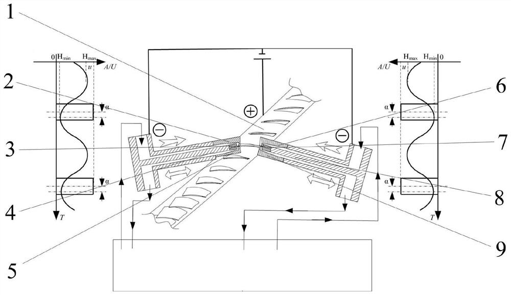
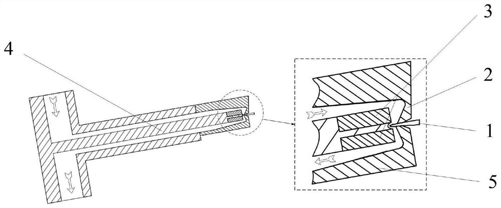
The invention discloses a blade or blisk air intake and exhaust edge pulse dynamic electrolysis shaping device. The blade or blisk air intake and exhaust edge pulse dynamic electrolysis shaping device comprises an air intake edge tool cathode, an air intake edge liquid admission guide plate, an air intake edge liquid discharging guide plate, an air intake edge insulation block, an air exhaust edge tool cathode, an air exhaust edge liquid admission guide plate, an air exhaust edge liquid discharging guide plate and an air exhaust edge insulation block. The intake edge tool cathode / the air exhaust edge tool cathode is adopted for accurate shaping in the optimal feeding direction of the air intake edge end / the exhaust edge end of the blade; electrolyte enters the air intake edge tool cathode / the air exhaust edge tool cathode from a liquid inlet in the upper side of the air intake edge tool cathode / the air exhaust edge tool cathode, flows to a machining area from a flow channel defined by the air intake edge liquid admission guide plate / the air intake edge liquid discharging guide plate and the air intake edge tool cathode / the air exhaust edge tool cathode, and flows through the molded surface of the end part of the air intake side / the exhaust side of a blank; and the liquid flows out of the machining area from the flow channel defined by the air intake side liquid discharging guide plate / the air exhaust side liquid discharging guide plate and the air intake side tool cathode / the air exhaust side tool cathode and finally flows out. Machining can be carried out under the condition that the machining gap is far smaller than a conventional machining gap, so that the contour precision of the air intake edge / the air exhaust edge of the blade / the blisk is remarkably improved.

Description

technical field [0001] The invention relates to the technical field of electrolytic machining, in particular to a dynamic electrolytic shaping device for the intake and exhaust side veins of a blade or an integral blade disk. Background technique [0002] With the continuous development of the aviation industry, the requirements for the performance of aero-engines are getting higher and higher. In order to reduce the weight of the engine and improve the overall performance of the engine, it has become inevitable to replace the traditional tenon-tenon-groove assembly structure with an integral blisk structure. trend. The blisk is the core component of an aero-engine, and its processing quality directly affects the aerodynamic performance of the engine. On the overall blisk, the intake / exhaust edge is the most important functional part. It divides and merges the high-speed airflow so that the airflow fits the blade profile and transmits power. If the machining accuracy of the...

Claims


Application Information

Patent Timeline
IPC IPC(8): B23H3/00B23H3/10
CPCB23H3/00B23H3/10
Inventor 朱荻刘嘉汪浩王京涛
Owner NANJING UNIV OF AERONAUTICS & ASTRONAUTICS
Learn More