Spiral, twill electrolysis electrode head and preparation method of electrode head for electrolysis

A technology of electrolytic electrodes and electrode heads, which is applied in the direction of electrode manufacturing, processing electrodes, electric processing equipment, etc., can solve the problems of high technical requirements, high cost, short service life, etc., and achieve the effect of high electrolytic processing precision and easy processing

Inactive Publication Date: 2017-01-18
GUANGDONG UNIV OF TECH
View PDF1 Cites 0 Cited by
  • Summary
  • Abstract
  • Description
  • Claims
  • Application Information

AI Technical Summary

Problems solved by technology

It is difficult to prepare the spiral electrode head for electrolysis by machining, especially for the spiral electrode head with variable cross-section, large lead, and multiple heads, which requires high technical requirements and high preparation price
It is difficult to cut a helical groove on a tapered table by machining
If the prepared electrode head is not cylindrical or conical, the required process is more complicated
It is achievable to mask the spiral shape on the curved surface of the cylinder or truncated cone by masking, but the required process is also more complicated, and the mask layer of the masked electrode tip is easy to fall off during processing. The service life is short. If the service life is to be long, the requirements for the masking process are higher. The mask layer must have high adsorption and strong corrosion resistance, so the cost is higher.
[0007] It can be seen that the cost of preparing the spiral electrode head for electrolysis by the existing machining method is high, and the flexibility of making various parameters is poor; the cost of masking the spiral electrode head by the method of masking is high, and the service life of the masked electrode head for actual processing is low. And it will fall off during the actual processing, which will affect the processing quality; in addition, the mask electrode head has high requirements on the mask process, and it is very difficult to realize

Method used


Image

  • Spiral, twill electrolysis electrode head and preparation method of electrode head for electrolysis
  • Spiral, twill electrolysis electrode head and preparation method of electrode head for electrolysis
  • Spiral, twill electrolysis electrode head and preparation method of electrode head for electrolysis

Examples


Embodiment Construction

[0025] The specific implementation manner of the present invention will be further described below in conjunction with the accompanying drawings.

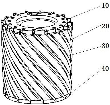
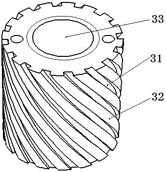
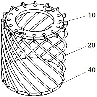
[0026] Such as figure 1 , figure 2 , image 3 As shown, a spiral electrolysis electrode tip of the present invention includes a cylindrical or elliptical column or a circular truncated insulating electrode tip body 30, a spiral groove 31 arranged on the peripheral surface of the electrode tip body 30, and embedded in the electrode tip body. The wire 20 in the groove 31, the upper conductive plate 10 and the lower connecting plate 40 that are arranged on the two ends of the electrode head body 30 and are fixedly conductively connected with the two ends of the wire 20, and the conductive rod that passes through the upper conductive plate 10 and is connected to the electrode head body 30 (not shown in the figure), the conductive rod has a shoulder abutting against the upper conductive plate 10 , and the depth of the groove 31 is 50...


PUM


Abstract

The invention discloses a spiral electrolytic electrode tip. The spiral electrolytic electrode tip comprises a cylindrical or circular table shaped insulating electrode tip body, spiral grooves formed at the circumference of the electrode tip body, lead wires embedded into the grooves, an upper conducting plate and a lower connecting plate arranged at the two end faces of the electrode tip body and fixedly and conductively connected with the two ends of the lead wires, and a conducting rod penetrating through the upper conducting plate and connected with the electrode tip body, wherein the conducting rod is provided with a shaft shoulder abutted against the upper current-conducting plate, and the grooves are 50 micrometers deeper than the lead wires. The lead wires are lower than the circumference surface where the grooves are located, so that an electrolytic solution can conveniently flow through gaps between the lead wires and workpieces; the lead wires are fixed by the upper conducting plate and the lower connecting plate, so that the whole electrode tip is easy to process; neither film masking nor complicated machining is required; and the electrode tip is stable in structure and long in service life, and has high degree of precision. The invention also discloses a twill electrolytic electrode tip easy to process, long in service life and high in precision, and further discloses a fabrication method of the electrolytic electrode tip easy to process, long in service life and high in precision..

Description

technical field [0001] The invention relates to an electrolysis electrode head, in particular to a spiral electrolysis electrode head and a diagonal electrolysis electrode head. The invention also relates to a method for preparing an electrode head for electrolysis. Background technique [0002] In the power electronics industry, the high frequency and high speed of microelectronic devices and the density and miniaturization of integrated circuits make the dissipation power of electronic devices increase rapidly, and the heat generation increases sharply. Conventional cooling methods can no longer meet the requirements. Electronic devices The heat dissipation has become a bottleneck in its development. [0003] Enhanced heat transfer technology refers to a new energy-saving technology that can significantly improve heat transfer performance. Micro heat pipes with enhanced heat transfer structures have become ideal components for heat conduction in high heat flux density mi...

Claims


Application Information

Patent Timeline
Patent Type & Authority Patents(China)
IPC IPC(8): B25H3/04
CPCB23H3/04
Inventor 王冠何宇斌孙涛涛于兆勤郭钟宁韦鸿钰陈少国
Owner GUANGDONG UNIV OF TECH
Why Eureka
Try Eureka