Agricultural anti-sinking soil turning vehicle
An anti-sinking and front-end technology is applied in vehicle maintenance, lifting vehicle accessories, and tilting vehicles that carry motion. Reduce time-consuming and increase the effect of the force-bearing surface
- Summary
- Abstract
- Description
- Claims
- Application Information
AI Technical Summary
Problems solved by technology
Method used
Image
Examples
specific Embodiment approach 1
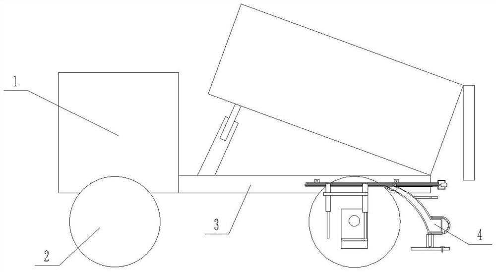
[0017] Specific implementation mode one: as Figure 1-9 As shown, this embodiment describes an agricultural anti-sink dumper, including a headstock 1, a wheel 2, a bracket 3 and a protective device 4; Wheel 2 is provided, and the dump bucket of the dump truck is hinged on the upper end of support 3;
specific Embodiment approach 2
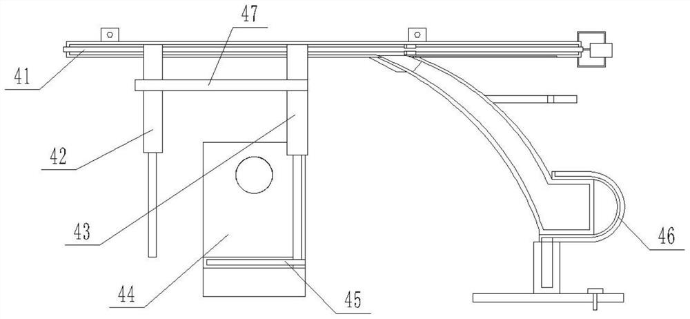
[0018] Specific implementation mode two: as figure 2 As shown, this embodiment is a further description of Embodiment 1. The protective device 4 includes a transmission device 41, a support device I42, a support device II43, a fixing device 44, a slide plate 45, a sliding device 46 and a connecting device 47; The support device I42 and the support device II43 are all connected to the transmission device 41, and the lower end of the support device II43 is fixedly connected with a slide plate 45; the fixation device 44 is fixedly connected to the outer side of the hub 5, and the slide plate 45 and the fixation device 44 are slidably matched The transmission device 41 is fixedly connected to the side of the bracket 3 ; the sliding device 46 is arranged at the lower end of the transmission device 41 .
specific Embodiment approach 3
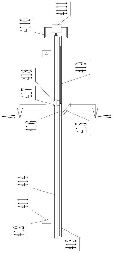
[0019] Specific implementation mode three: as image 3 , 4 As shown, this embodiment is a further description of Embodiment 1. The transmission device 41 includes two connecting pieces 411, connecting bolts I 412, support frame 413, screw rod 414, limit plate 415, and two stop rods 417. , two connection blocks 418, a motor bracket 4110 and a motor 4111; the middle of the support frame 413 is provided with a cavity, and the top of the support frame 413 is fixedly connected with two connection pieces 411, and the connection piece 411 is fixed on the The side of the bracket 3; the motor 4111 is fixedly connected to the side of the support frame 413 through the motor bracket 4110, and the output shaft of the motor 4111 is fixedly connected with a screw rod 414; the screw rod 414 passes through the support frame 413, and the screw rod 414 is connected by a bearing On the support frame 413; the support device I42 is slidingly fitted with the screw rod 414; the support device II43 i...
PUM
 Abstract
Description
Claims
Application Information
 - R&D Engineer
- R&D Manager
- IP Professional
- Industry Leading Data Capabilities
- Powerful AI technology
- Patent DNA Extraction
Browse by: Latest US Patents, China's latest patents, Technical Efficacy Thesaurus, Application Domain, Technology Topic, Popular Technical Reports.
© 2024 PatSnap. All rights reserved.Legal|Privacy policy|Modern Slavery Act Transparency Statement|Sitemap|About US| Contact US: help@patsnap.com


