
Offshore wind power unit foundation

An offshore wind power and basic technology, applied in basic structure engineering, animal husbandry, applications, etc., can solve problems such as increasing the difficulty of basic processing, and achieve the effect of maximizing economical utility and maximizing functions

Pending Publication Date: 2021-08-06
POWERCHINA ZHONGNAN ENG
View PDF1 Cites 0 Cited by
  • Summary
  • Abstract
  • Description
  • Claims
  • Application Information

AI Technical Summary

Problems solved by technology

[0005] An offshore wind power foundation disclosed in an existing patent such as Publication No. CN110027685A adopts the addition of several openings for fish to pass through and inhabit in the gravity foundation to provide an artificial reef using the foundation of the offshore wind turbine. Technical solution, but the opening is directly set on the foundation, thus increasing the processing difficulty of the foundation

Method used


Image

  • Offshore wind power unit foundation
  • Offshore wind power unit foundation
  • Offshore wind power unit foundation

Examples


Embodiment 1

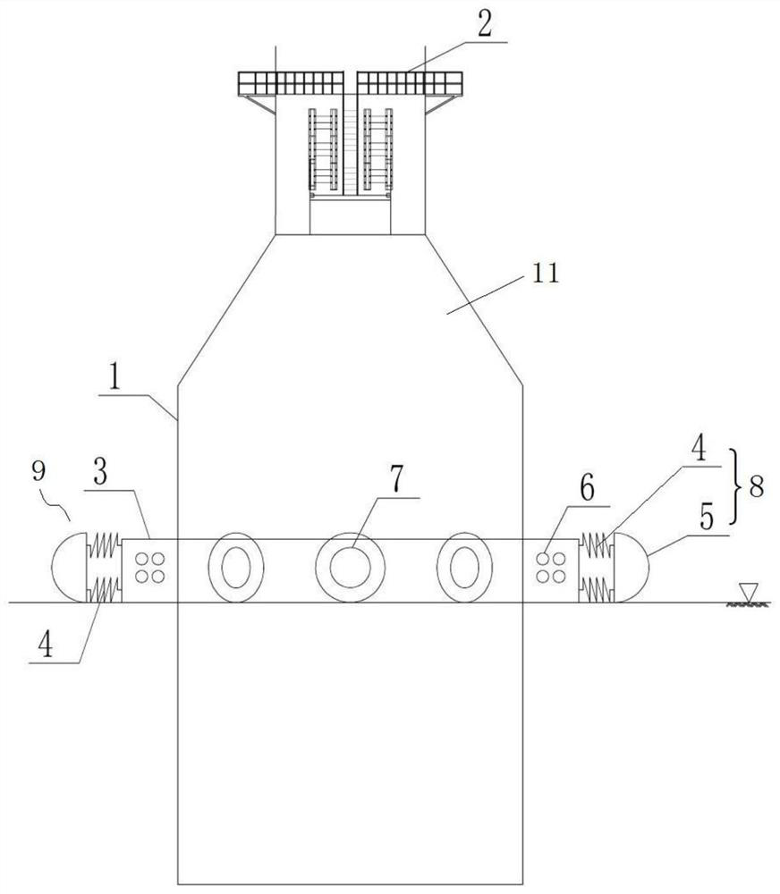
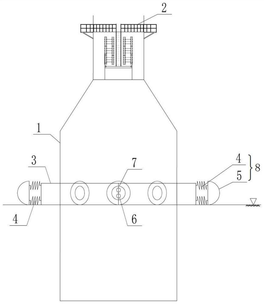
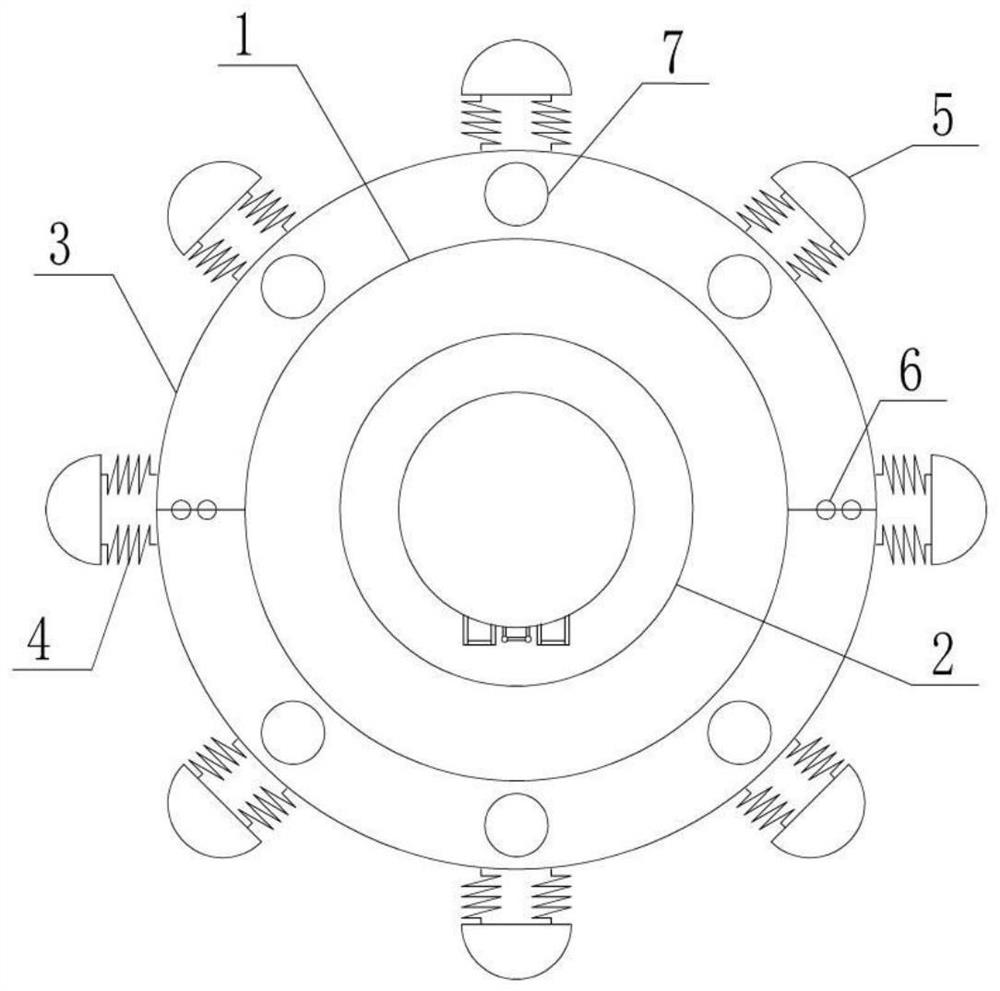
[0046] Such as figure 1 , figure 2 As shown, the offshore wind farm foundation provided by this embodiment includes a foundation body 1 and an artificial reef 9 . The artificial reef 9 includes a casing 3 and an energy dissipation component 8 . The casing 3 is a container, which is arranged around the basic body 1, and the vertical side and the top of the casing 3 are provided with a plurality of holes 7 penetrating the container wall. The hole 7 is for fish to swim in or out.

[0047] In this embodiment, the foundation body 1 is a monopile foundation, which includes a pipe pile 11 , and the pipe pile 11 is made of steel, and an accessory member 2 is arranged on the top thereof. The casing 3 is a ring matching the shape of the pipe pile 11 . The ring is a hollow cylindrical structure.

[0048]The casing 3 is a ring formed by assembling two semicircular steel cylinders, and the inner wall of the ring of the casing 3 is attached to the outer wall of the pipe pile 11 . And...

Embodiment 2

[0054] Such as Figure 4~Figure 7 As shown, the first embodiment is repeated, the difference is that the foundation body 1 in the offshore wind power group foundation provided by this embodiment is a stand-type foundation, which includes a stand 12 and a pipe pile 11, and the stand The bottom of the frame 12 is provided with at least three pipe piles 11, and one artificial fish reef 9 is set on each pipe pile 11. The top of the stand 12 is the accessory component 2 .

[0055] Such as Figure 7 As shown, the casing 3 is a ring formed by assembling two half-ring steel cylinders with the same shape, and is fixed with a fastener 6 at the assembling place. The inside of the casing 3 is provided with a circular hole matching the shape of the pipe pile 11 (the circular hole is a cylindrical hollow hole), so that the casing 3 forms a ring, and the inner wall of the ring is in contact with the foundation The outer wall of the corresponding installation part (pipe pile 11) on the bod...

Embodiment 3

[0058] Such as Figure 8~Figure 10 As shown, the first embodiment is repeated, the difference is that the foundation body 1 in the offshore wind power group foundation provided by this embodiment is a gravity foundation with a trumpet-type suction cylinder steel structure, which includes pipe piles 11, One artificial reef 9 is set on the pipe pile 11 , and the artificial fish reef 9 is arranged near the bottom of the pipe pile 11 . The casing 3 is a ring that matches the shape of the pipe pile 11 (such as Figure 10 shown).

[0059] In this embodiment, fourteen holes 7 are provided on the top of the casing 3 , and sixteen holes 7 are provided on the sides. The specific number of holes 7 is related to the area of ​​the top or side. In this embodiment, the number of energy dissipation components 8 is sixteen (such as Figure 10 shown).


PUM


Abstract

The invention provides an offshore wind power unit foundation. The offshore wind power unit foundation comprises a foundation body and an artificial fish reef; the artificial fish reef comprises a pouring jacket; the pouring jacket is a container and surrounds the foundation body; and a plurality of holes penetrating through the wall of the container are formed in each of the vertical side face and the top of the pouring jacket. Compared with related technologies, the offshore wind power unit foundation provided by the invention has the advantages that aiming at the characteristic of isolated layout of the wind power unit foundation, a set of pouring jacket which can adapt to the type and size of a single-pile type foundation is researched to form the artificial fish reef; for reducing the influence of seawater flow on oviposition and rest of fishes, a stable and quiet environment is provided for the oviposition and rest of the fishes by designing energy dissipation hemispheroids; the economy, practicability and function maximization of the artificial fish reef are achieved; and the integrated development of the offshore wind power unit foundation and the artificial fish reef is promoted.

Description

technical field [0001] The invention relates to the technical field of offshore wind power and sea farming, in particular to a foundation for an offshore wind power group. Background technique [0002] With the rapid development of global offshore wind power, more and more aquaculture sea areas have been expropriated and developed into offshore wind farms, which has led to increasingly prominent conflicts between offshore wind power and aquaculture sea areas, seriously hindering the development of offshore wind power, and overfishing. Factors such as the deterioration of the ecological environment and other factors have led to the depletion of marine fish resources, and the traditional marine aquaculture model is unsustainable. [0003] After the completion of the current offshore wind farm, the sea area is no longer completely open and unobstructed waters, and many isolated wind turbine foundations have been formed in the sea area. The short distance between the foundation...

Claims


Application Information

Patent Timeline
Patent Type & Authority Applications(China)
IPC IPC(8): E02D27/44E02D27/52F16F15/067A01K61/73
CPCA01K61/73E02D27/44E02D27/52F16F15/067Y02P60/60Y02A40/81
Inventor 刘功鹏潘江洋颜彪
Owner POWERCHINA ZHONGNAN ENG
Learn More