Arcuate-Winged Solar Canopy Assembly

a solar canopy and arcuate technology, applied in the direction of solar heat collector mounting/support, solar heat collector safety, light and heating apparatus, etc., can solve the problems of not being ideal, rigid and expensive assembly, and maximizing the value and use of airspace, so as to facilitate the use of solar power collected, increase thickness, and maximize the effect of functionality

Active Publication Date: 2014-05-29
RICHARDSON DONALD S
View PDF13 Cites 20 Cited by
  • Summary
  • Abstract
  • Description
  • Claims
  • Application Information

AI Technical Summary

Benefits of technology

[0028]To facilitate use of the solar power collected by the canopies, the assembly can include at least one inverter to convert direct current from the solar collection means to alternating current for storage and / or distribution. In addition, to maximize its functionality, the system can include at least one vehicle charging outlet, the outlet being able to draw electric power from the inverter, or grid, to charge electric vehicles or other equipment.
[0029]In another aspect, the invention comprises a kit for constructing an arcuate winged solar canopy comprising least two pairs of dual-inclined wing structural arms. The arms are composed of a first pair of low-incidence, downwardly-curved or arcuate wing arms and a second pair of low-incidence, downwardly curved or arcuate wing arms. Each of the first and second pairs of downwardly-curved arcuate wing arms has a proximal end and distal end. The proximal ends in each pair are arranged to be in opposed relation to each other forming a structural spine in the assembly. The curvature in the downwardly-sloping, arcuate, wing arms begins at the distal ends of the wing arms and increases in steepness toward the proximal ends of the arms and the structural spine. For stability, the wing arms increase in thickness from their distal ends, which are relatively thin, to their proximal ends, which are relatively thick. In other words, beginning from the proximal ends, the wings arms taper in thickness approaching the distal end, and terminate in a tapered end.

Problems solved by technology

Solar panels placed atop free standing structures combine power generation with, for example, shade production, which results in the maximization of the value and use of the airspace.
Certain problems are associated with the foregoing and similar approaches.
This makes them not readily accessible, often compromises roof integrity, and results in a rigid and expensive assembly.
In addition, conventional rooftop solar arrays are typically designed and disposed along a single slope plane, which may not be ideal in some locales.
Further, such installations are problematic when there is snow or ice buildup in the winter.
Still further, inclined, fixed plane canopies with mono-planar wings cannot maximize solar collection capability without adjustment to the wing angle.
While such major footings presented a stable structure, the approach is now considered deficient in that major excavation work is necessary to accommodate the footings and, where applicable, the water containment vessels.
The required excavation for such foots is significant and disruptive to the work site.
Still further, the concrete required to form the footings has a large carbon footprint, is relatively expensive to make and transport, and has a very long and negative energy tail such that it is not environmentally benign.
Even further, installation of the footings required tons of gravel as a backfill and as a drainage element enveloping the subsurface elements, again having negative energy repercussions.
The large concrete footings also demanded substantial formwork, cost, and cure time during the installation process.
Disadvantageously, forming such structurally supportive projections demands very deep composite casting forms at the proximal end of the wings.
Milling such casting forms has proven to be complicated and awkward, and the creation of the resulting proximal ends to be time and labor intensive.
Additionally, it has been found that the resulting semi-circular sections and flanges results in an undesirable aesthetic solution and that the structural integrity and durability of the formed dual wing arm structure is dependent, potentially disadvantageously so, on the performance of the fastening mechanism coupling the flanges.
Still further, as a result of the protruding proximal ends where the flanges laterally project, the resulting wing arms prove difficult to stack for storage and transport.

Method used


Image

  • Arcuate-Winged Solar Canopy Assembly
  • Arcuate-Winged Solar Canopy Assembly
  • Arcuate-Winged Solar Canopy Assembly

Examples


Embodiment Construction

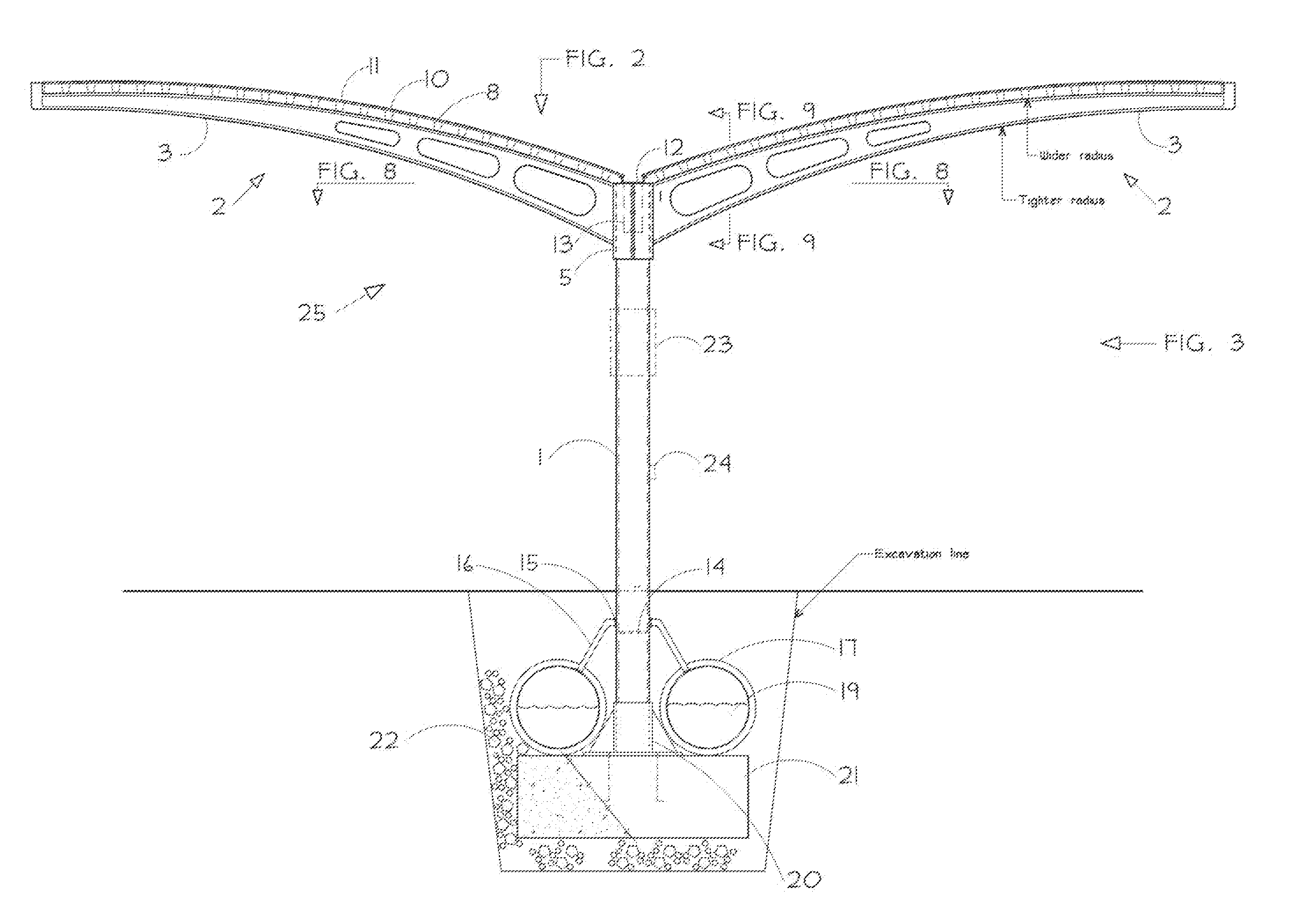
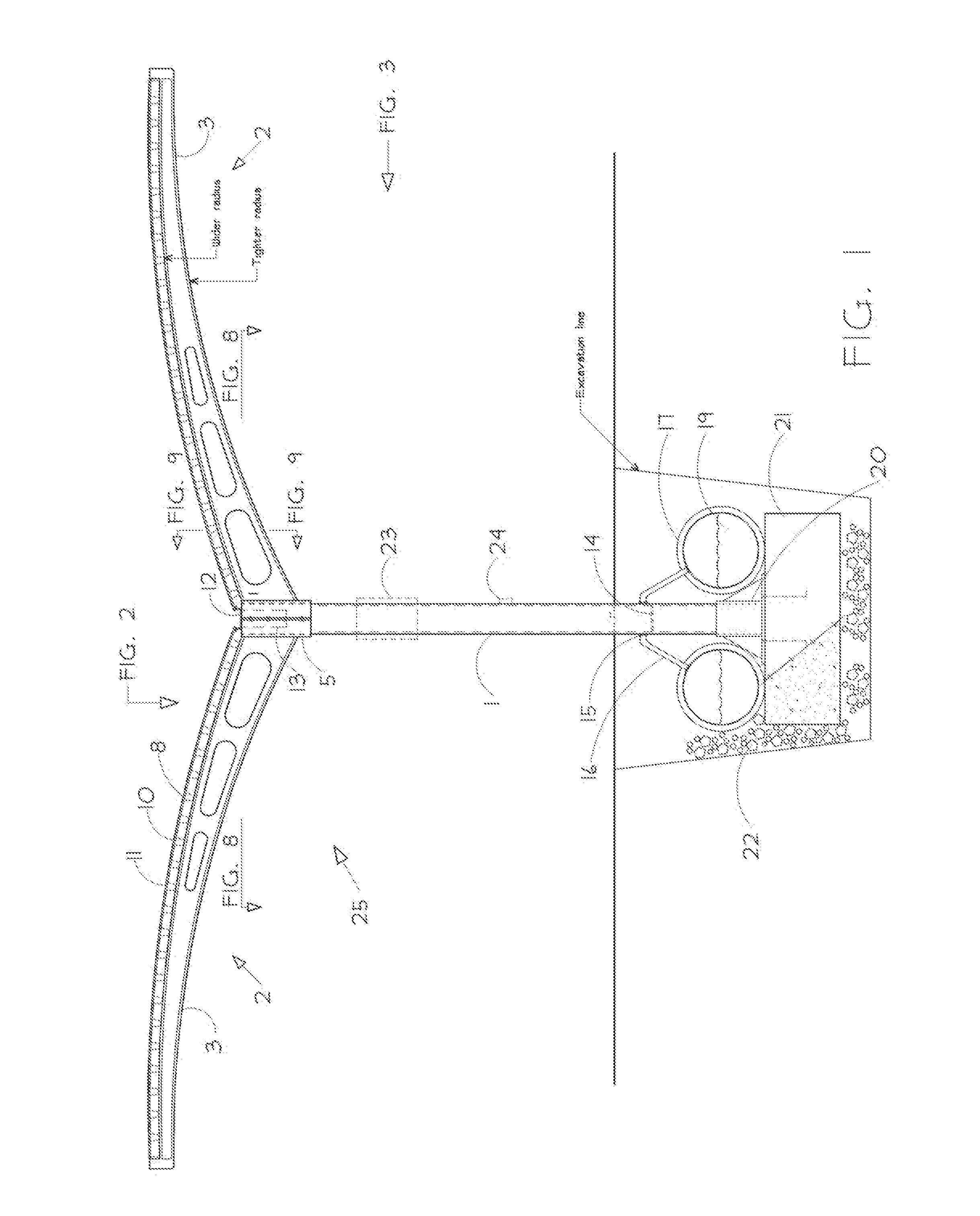
[0058]The solar canopy assembly disclosed herein is subject to widely varied embodiments. However, to ensure that one skilled in the art will be able to understand and, in appropriate cases, practice the present invention, certain preferred embodiments of the broader invention revealed herein are described below. Therefore, before any particular embodiment of the invention is explained in detail, it must be made clear that the following details of construction and inventive concepts are mere examples of the many possible manifestations of the invention.

[0059]FIG. 1 shows a preferred embodiment of the canopy assembly 25. In FIG. 1, canopy assembly 25 is composed of support column 1 which extends substantially vertically from below ground level to a height sufficient to permit the parking of vehicles or storage of equipment under attached wing member 2. Support columns 1 may have a cylindrical shape, although other shapes may be employed, such as, but not limited to, an open box, octo...


PUM


Abstract

A solar canopy structure mounted in ground to receive solar energy and convert the solar energy to electrical energy. The solar canopy structure has support columns, solar canopies retained in opposition by the support column, photovoltaic material retained by the solar canopies, and a block of material establishing a point of fixation along the body portion of the support column spaced from the first and second ends of the support column. At least approximately one-half of the support column can be embedded in the ground with the block of material fixed to the support column adjacent to the ground surface. The solar canopies can be have decking supported by wing arms that are joined by a central portion to form a unified, continuous wing arm structure, and the central portion can be received in and secured to a channel in the support column by first and second brackets.

Description

FIELD OF THE INVENTION[0001]The invention relates to a lightweight, easy to assemble, arcuate-winged solar canopy assembly that that combines electric power generation with various additional uses.BACKGROUND[0002]Solar panels placed atop free standing structures combine power generation with, for example, shade production, which results in the maximization of the value and use of the airspace. Freestanding structures that generate electric or wind power from rooftop devices to electrically charge and run vehicles are known in the art. See for example, Japanese Patent Publication No. 09-002259, U.S. Pat. No. 6,590,363 and United States Patent Publication No. 2010 / 0000596 published Jan. 7, 2010. More specifically, JP 09-002259 discloses a photovoltaic power generation apparatus and a cartridge-type storage battery for a vehicle, for example a train, which can be exchanged when the vehicle is parked in a charging station having the photovoltaic power generation mounted on its roof. U.S...

Claims


Application Information

Patent Timeline
Patent Type & Authority Applications(United States)
IPC IPC(8): H01L31/042
CPCH01L31/0422Y02E10/50Y02B10/20E04H6/025Y02E10/47H02S20/00H02S20/10E04H6/10F24S25/617F24S20/67F24S40/44F24S25/10Y02B10/10H01L31/042
Inventor RICHARDSON, DONALD S.
Owner RICHARDSON DONALD S
Why Eureka
Try Eureka