Rainwater collecting and recycling device

A rainwater collection and reuse technology, applied in water supply installations, drinking water installations, general water supply conservation, etc., can solve problems such as falling leaves and affecting rainwater collection

Inactive Publication Date: 2021-08-06
付永贵
View PDF1 Cites 1 Cited by
  • Summary
  • Abstract
  • Description
  • Claims
  • Application Information

AI Technical Summary

Problems solved by technology

[0004] Existing trees are generally irrigated through the irrigation system. In order to save resources, some rainwater collection devices will be added. However, the existing rainwater collection devices are generally installed between trees. The leaves on the trees wither and fall, and the rainwater collection During the rainwater collection process of the device, some leaves fall onto the rainwater collection device, which affects the collection of rainwater

Method used


Image

  • Rainwater collecting and recycling device
  • Rainwater collecting and recycling device
  • Rainwater collecting and recycling device

Examples


Embodiment 1

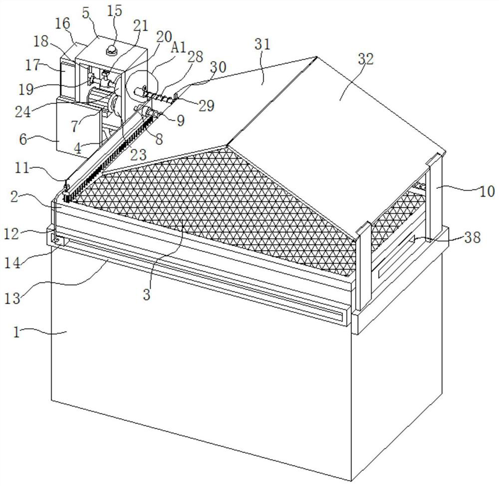
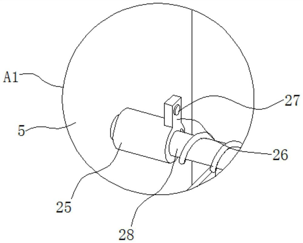
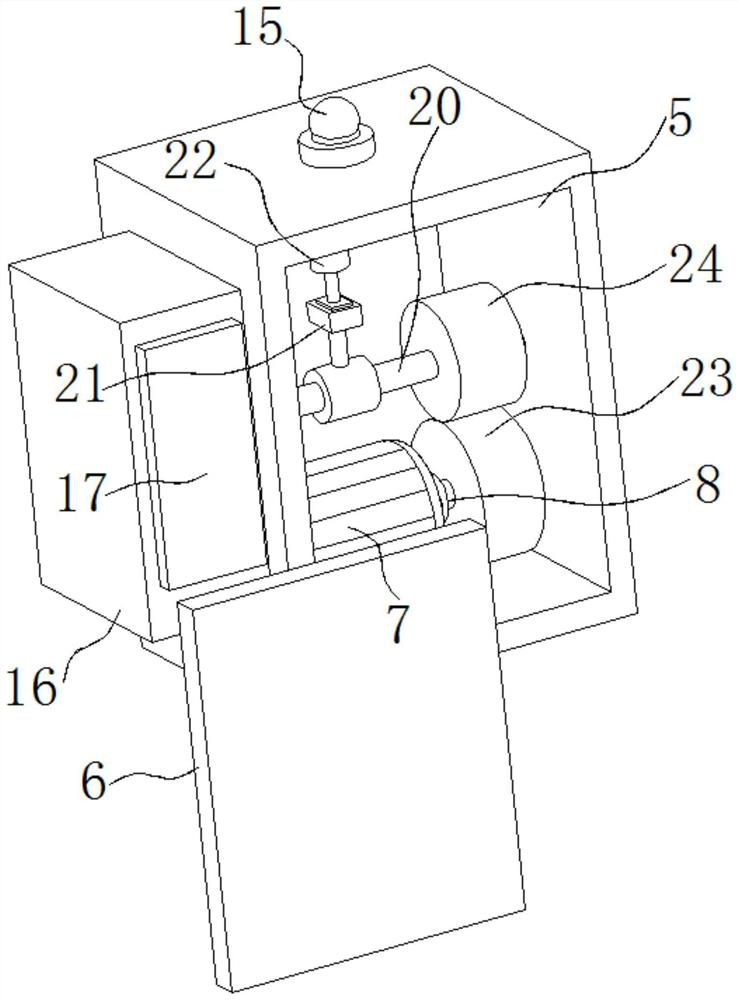
[0026] refer to Figure 1-7 , a rainwater collection and reuse device, comprising a collection box 1, the upper end of the collection box 1 is connected with a first fixed frame 2, the first fixed frame 2 is connected with a filter screen 3, the filter screen 3 filters sundries in rainwater, and collects One side of the box 1 is connected with a support frame 4, the other side of the collection box 1 is connected with a fixed frame 10, the upper end of the support frame 4 is connected with a box body 5, the outside of the box body 5 is sprayed with an anti-corrosion layer, and the box body 5 is connected There is an inspection panel 6, and a gasket is connected to the inspection panel 6. The gasket is located at the junction of the inspection panel 6 and the box body 5, so as to prevent rainwater from entering the box body 5 from the gap between the inspection panel 6 and the box body 5. The box body 5 is connected with a motor 7, the output end of the motor 7 is driven and co...

Embodiment 2

[0029] In non-rainy weather, the upper end of the filter screen 3 tends to accumulate more leaves and sundries, causing the brush 11 to start to fail to quickly clean the leaves and sundries at the top of the filter screen 3 after it rains, causing rainwater to fail to enter the collection box 1. refer to Figure 1-7, as another preferred embodiment of the present invention, on the basis of Embodiment 1, a first chute 18 is opened inside the box body 5, and a second slider 19 is slidably connected in the first chute 18, and the second The slider 19 is rotatably connected with a second rotating shaft 20, which drives the second reciprocating screw 28 to rotate after the second rotating shaft 20 rotates. The inner upper end of the box body 5 is connected with a lifting assembly, and the lifting assembly is socketed on the second rotating shaft 20, and the lifting assembly Including a telescopic cylinder 22, the telescopic cylinder 22 is connected to the box body 5, the telescopi...

Embodiment 3

[0033] When the leaves above were shielded by the first baffle plate 31 and the second baffle plate 32 and fell onto the filter screen 3, there was still a large gap between the sides of the first baffle plate 31, the second baffle plate 32 and the filter screen 3. Large gaps, in windy weather, sand particles are easy to fall from the gaps to the filter screen 3, and then enter the collection box, refer to Figure 1-7 , as another preferred embodiment of the present invention, on the basis of Embodiment 2, second fixing frames 39 are connected to both sides of the lower surface of the first baffle plate 31, and each second fixing frame 39 is connected to a second fixing frame 39. An anti-sand net 40, the lower surface both sides of the second baffle plate 32 are connected with the third fixed frame 42, each third fixed frame 42 is connected with the second anti-sand net 43, the third fixed frame 42 is connected with the first fixed frame 42 The two fixed frames 39 are distribu...


PUM


Abstract

The invention relates to the technical field of agriculture and forestry planting, in particular to a rainwater collecting and recycling device. The rainwater collecting and recycling device comprises a collecting box, a box body is connected to the upper end of a supporting frame, a maintenance plate is connected to the box body, a motor is connected into the box body, and the output end of the motor is in driving connection with a first rotating shaft; and a first reciprocating screw is connected to one end of the first rotating shaft, one end of the first reciprocating screw is rotatably connected with a fixing frame, the first reciprocating screw is connected with a brush, a guide mechanism is connected with one end of the brush, and a rainwater sensor is connected with the upper end of the box body. The first rotating shaft rotates to drive the first reciprocating screw to rotate, the first reciprocating screw rotates to drive the brush to move, a first sliding block slides in a sliding rail in the brush moving process, so that the brush stably moves in the horizontal direction, the brush is driven by the first reciprocating screw to reciprocate in the horizontal direction, sundries at the upper end of a filter screen are swept, and rainwater is prevented from entering the collecting box due to accumulation of the sundries.

Description

[0001] This application is a divisional application, the original patent number is: 202010932158.8, the application date is September 08, 2020, and the title of the invention is: a rainwater collection and reuse device for agricultural and forestry planting. technical field [0002] The invention relates to the technical field of agriculture and forestry planting, in particular to a rainwater collection and reuse device. Background technique [0003] The development of the agricultural and forestry economy is directly related to the country's economic construction and social development. my country's agricultural development is constantly strengthening and improving. Trees can not only provide the economy, but also purify the air. Water and nutrients are needed during tree planting. [0004] Existing trees are generally irrigated through the irrigation system. In order to save resources, some rainwater collection devices will be added. However, the existing rainwater collecti...

Claims


Application Information

Patent Timeline
Patent Type & Authority Applications(China)
IPC IPC(8): E03B3/02B01D29/01B01D29/64
CPCE03B3/02B01D29/01B01D29/6423Y02A20/108
Inventor 不公告发明人
Owner 付永贵
Why Eureka
Try Eureka