Ball valve

A technology of ball valves and valve balls, which is applied in the field of pipeline valves, can solve the problems of affecting the sealing effect and service life of ball valves, affecting the normal operation of the system, and wear of valve balls and seals, so as to prolong the continuous service life, save manual operation, The effect of ensuring reliability

Inactive Publication Date: 2021-08-06
任林赟
View PDF0 Cites 0 Cited by
  • Summary
  • Abstract
  • Description
  • Claims
  • Application Information

AI Technical Summary

Problems solved by technology

However, during the opening and closing process of the ball valve, the rotation of the valve ball will cause friction between the seal and the valve ball, which will cause wear to the valve ball and the seal after working for a long time, affecting the sealing effect and service life of the ball valve. It is necessary to maintain the ball valve in time. The current maintenance of the ball valve is to remove it from the pipeline. Frequent disassembly and maintenance are not only cumbersome, but also affect the work of the entire system, especially when the pipeline needs to be kept disconnected. When opening, the sudden failure of the sealing of the ball valve will directly affect the normal operation of the entire system, and even cause safety hazards

Method used


Image

  • Ball valve
  • Ball valve
  • Ball valve

Examples


Embodiment Construction

[0022] The technical solutions of the present invention will be further described in detail below in conjunction with the accompanying drawings and embodiments.

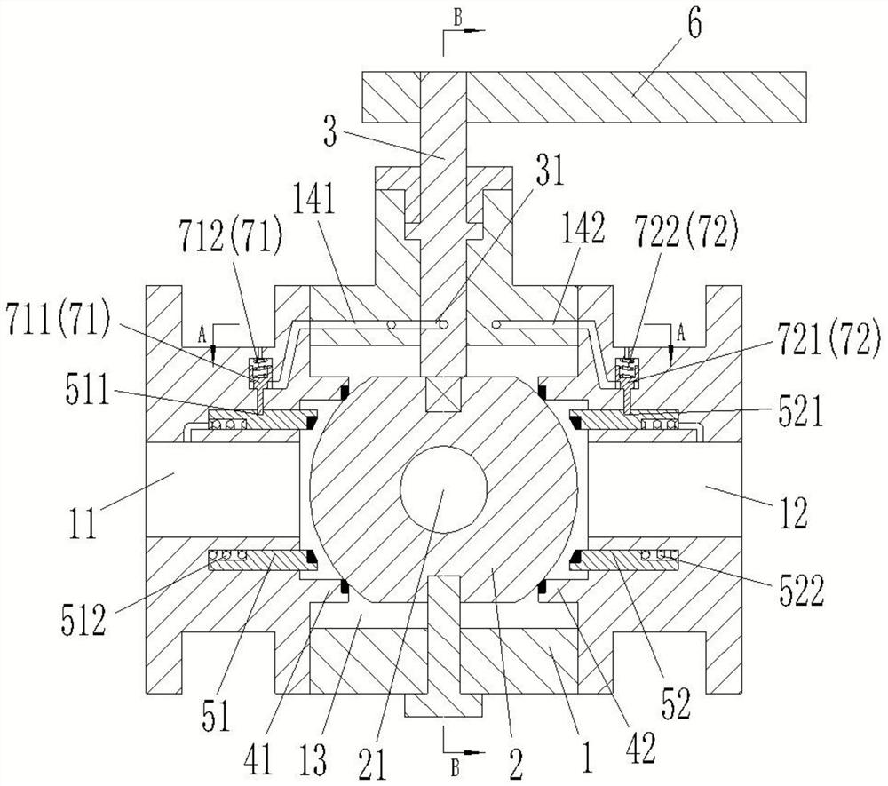
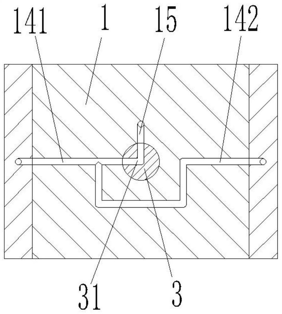
[0023] combine Figure 1 to Figure 4 As shown, the ball valve in this embodiment includes a valve body 1 , a valve ball 2 , a drive shaft 3 , a first inlet valve seat 41 , a first outlet valve seat 42 , a second inlet valve seat 51 and a second outlet valve seat 52 .

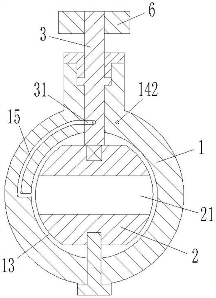
[0024] The valve body 1 adopts a split structure and is formed by connecting multiple components, and the valve body 1 is provided with an inlet 11 and an outlet 12 connected with external pipes. The valve ball 2 is located between the inlet 11 and the outlet 12 inside the valve body 1 and is provided with a flow hole 21 .

[0025] One end of the drive shaft 3 is located outside the valve body 1 and is provided with a handle 6. The other end of the drive shaft 3 extends into the inside of the valve body 1 and is fixedly connected with the valve ball 2...


PUM


Abstract

The invention belongs to the technical field of pipeline valves and discloses a ball valve. The ball valve comprises a valve body, a valve ball, a driving shaft, a first inlet valve seat, a first outlet valve seat, a second inlet valve seat and a second outlet valve seat; the first inlet valve seat and the first outlet valve seat are located at the inlet position and the outlet position in the valve body respectively and form normal contact sealing with the valve ball; the second inlet valve seat and the second outlet valve seat are located at the inlet position and the outlet position in the valve body respectively and form selective contact sealing with the valve ball; and when the sealing between the first inlet valve seat and / or the first outlet valve seat and the valve ball fails, the second inlet valve seat and the second outlet valve seat respectively move relative to the valve body and respectively form contact sealing with the valve ball. According to the ball valve provided by the invention, double-seal switching can be achieved, the anti-leakage effect is improved, and the ball valve has the longer service life.

Description

technical field [0001] The invention belongs to the technical field of pipeline valves, and in particular relates to a ball valve. Background technique [0002] The ball valve is mainly used to cut off, distribute and change the flow direction of the medium in the pipeline. It only needs to rotate 90 degrees and a small rotational torque to close the ball valve tightly. It has the advantages of small fluid resistance and simple structure. . As the opening and closing part of the ball valve, the valve ball is driven by the valve stem and rotates around the axis of the ball valve, which can be used for fluid adjustment and control. [0003] Due to the specific structure of the ball valve, the seal on the valve seat needs to be tightly attached to the valve ball to achieve the sealing of the closed state of the ball valve. However, during the opening and closing process of the ball valve, the rotation of the valve ball will cause friction between the seal and the valve ball, ...

Claims


Application Information

Patent Timeline
Patent Type & Authority Applications(China)
IPC IPC(8): F16K5/06F16K5/08F16K27/06
CPCF16K5/0663F16K5/08F16K27/067
Inventor 任林赟李鹤张云杰
Owner 任林赟
Why Eureka
Try Eureka