
Electro-hydraulic co-rotating joint

A technology of rotating joints and common bodies, which is applied in the direction of rotating current collectors, circuits, current collectors, etc., can solve the problems of large volume, difficulty in realizing rotating joints, and difficulty in ensuring rotation accuracy, etc., and achieves small size, reduced quantity and volume , the effect of compact structure

Active Publication Date: 2021-08-06
CHINA ELECTRONIC TECH GRP CORP NO 38 RES INST
View PDF7 Cites 0 Cited by
  • Summary
  • Abstract
  • Description
  • Claims
  • Application Information

AI Technical Summary

Problems solved by technology

Whether it is an axial stacking combination or a radial nesting combination, the volume is large, and the rotation accuracy is difficult to guarantee
At present, many electronic equipment systems have particularly high requirements for function, precision, heat dissipation, and miniaturization. It is difficult to realize the rotary transmission of electro-hydraulic or photoelectric liquid media in an extremely limited space, which is difficult for traditional multi-functional multi-media rotary joints.

Method used


Image

  • Electro-hydraulic co-rotating joint
  • Electro-hydraulic co-rotating joint
  • Electro-hydraulic co-rotating joint

Examples


Embodiment Construction

[0022] The above and other technical features and advantages of the present invention will be described in more detail below in conjunction with the accompanying drawings.

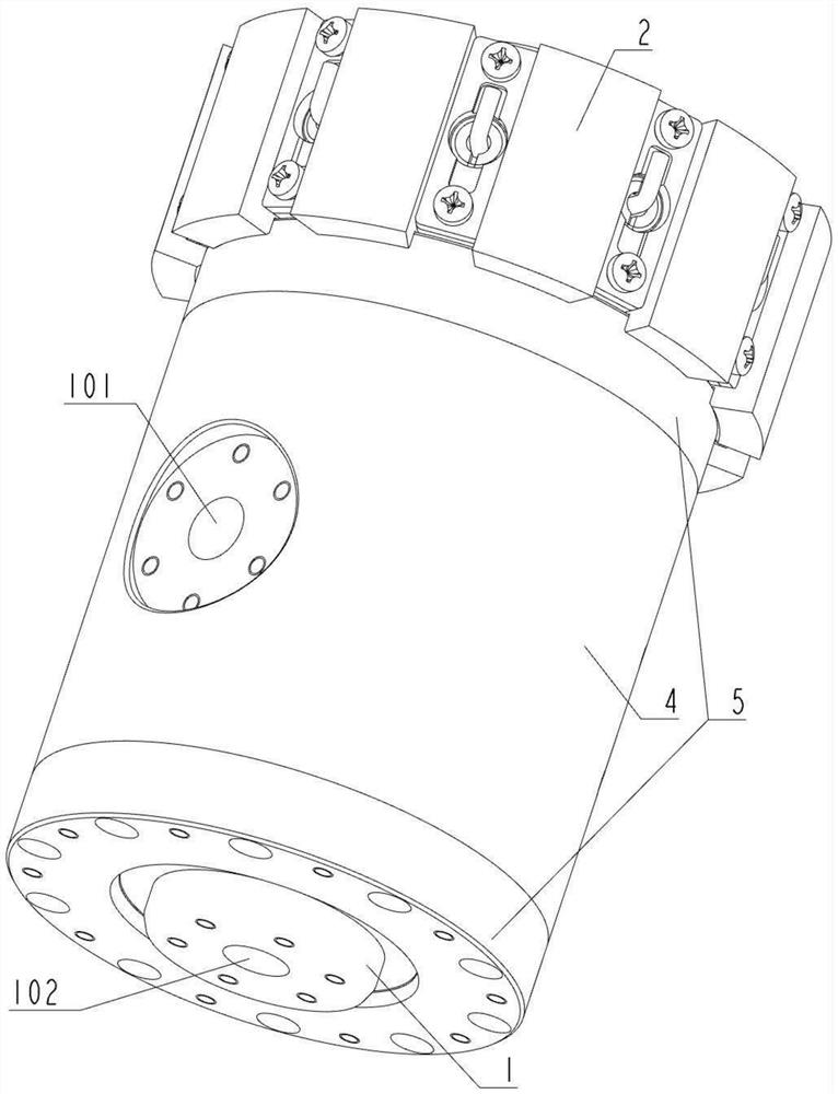
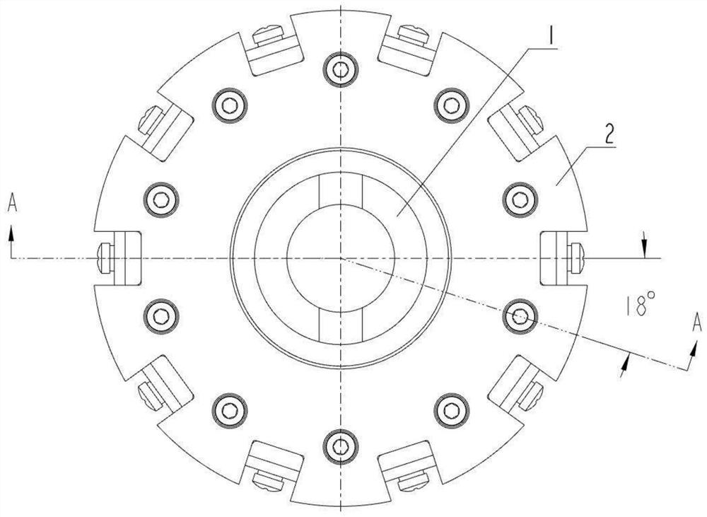
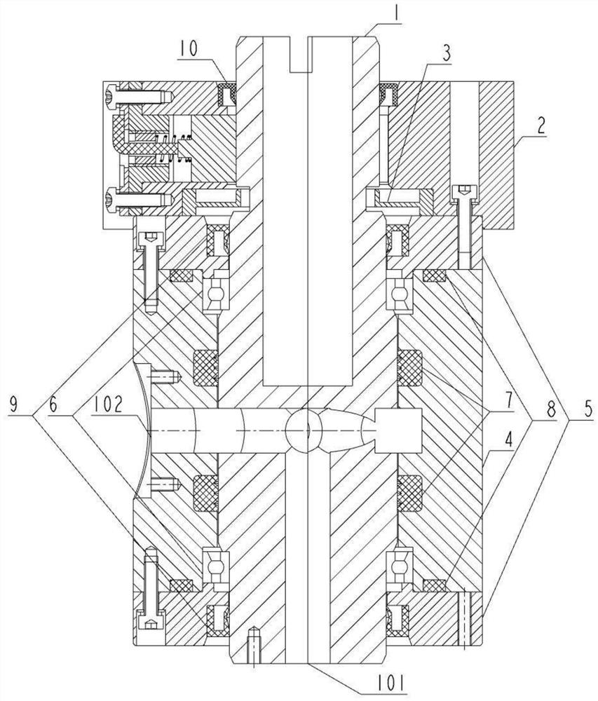
[0023] Such as Figure 1 to Figure 5 as shown, figure 1 It is a three-dimensional structure diagram of the electro-hydraulic body rotary joint; figure 2 It is a top view of the structure of the electro-hydraulic body rotary joint; image 3 for figure 2 The cross-sectional view of A-A in the middle; Figure 4 It is a three-dimensional structure diagram of the brush assembly;

[0024] Figure 5 It is a cross-sectional view of the brush assembly. The electro-hydraulic integrated rotary joint of the present invention includes an inner ring 1 and an outer ring arranged on the outer surface of the inner ring 1 , and the inner ring 1 and the outer ring can rotate relative to each other.

[0025] The outer ring includes a brush assembly 2, a powder receiving tray 3, a sealing housing 4 and a bearing retai...


PUM


Abstract

The invention discloses an electro-hydraulic co-rotating joint which comprises an inner ring and an outer ring arranged on the outer side face of the inner ring, and the inner ring and the outer ring can rotate relatively. The outer ring comprises an electric brush combination and a sealing shell; the electric brush combination and the sealing shell sleeve the inner ring, the electric brush combination is in contact connection with the inner ring through an electric brush, and the sealing shell is in contact connection with the inner ring; an outlet is formed in the sealing shell in the radial direction, an inlet is formed in the inner ring in the axial direction, an annular liquid flow channel is formed between the sealing shell and the inner ring, the outlet is communicated with the annular liquid flow channel, a plurality of connecting channels are formed in the inner ring in the radial direction, and two ends of each connecting channel are connected with the annular liquid flow channel and the inlet respectively; and the inlet, the connecting channel, the annular liquid flow channel and the outlet form a cooling liquid transmission channel. Under the condition of an extremely limited space, electro-hydraulic integrated design is carried out, the structure is compact, the same part can achieve rotary transmission of electric signals and rotary transmission of a cooling liquid, and meanwhile, the electric signals and the cooling liquid do not influence each other.

Description

technical field [0001] The invention relates to the technical field of electronic equipment rotary transmission devices, in particular to an electro-hydraulic composite rotary joint. Background technique [0002] With the continuous increase of power consumption of electronic equipment systems, the application requirements of multi-functional multimedia rotary joints in electronic equipment systems are becoming more and more urgent. The traditional multi-functional and multi-media rotary joints mostly adopt the form of a combination of rotary transmission devices with different media such as electric slip rings, smooth rings, and liquid rotary joints. Whether it is an axial stacking combination or a radial nesting combination, the volume is large, and the rotation accuracy is difficult to guarantee. At present, many electronic equipment systems have particularly high requirements for function, precision, heat dissipation, and miniaturization. It is difficult to realize the ...

Claims


Application Information

Patent Timeline
Patent Type & Authority Applications(China)
IPC IPC(8): F16L27/08F16L27/093H01R39/64H01R39/02
CPCF16L27/0849F16L27/093H01R39/64
Inventor 常健赵克俊李旺罗奕武康成彬刘文科查金水彭伟邓书山张瑞珏
Owner CHINA ELECTRONIC TECH GRP CORP NO 38 RES INST
Learn More