

Path planning method and cleaning robot
A path planning and cleaning technology, applied in the direction of instruments, vehicle position/route/height control, non-electric variable control, etc., can solve the problems of reducing cleaning efficiency, unscientific starting position and posture, spending more time, etc. The effect of cleaning efficiency, saving cleaning time and reducing the number of turns
- Summary
- Abstract
- Description
- Claims
- Application Information
AI Technical Summary
Problems solved by technology
Method used
Image

Examples
Embodiment 1
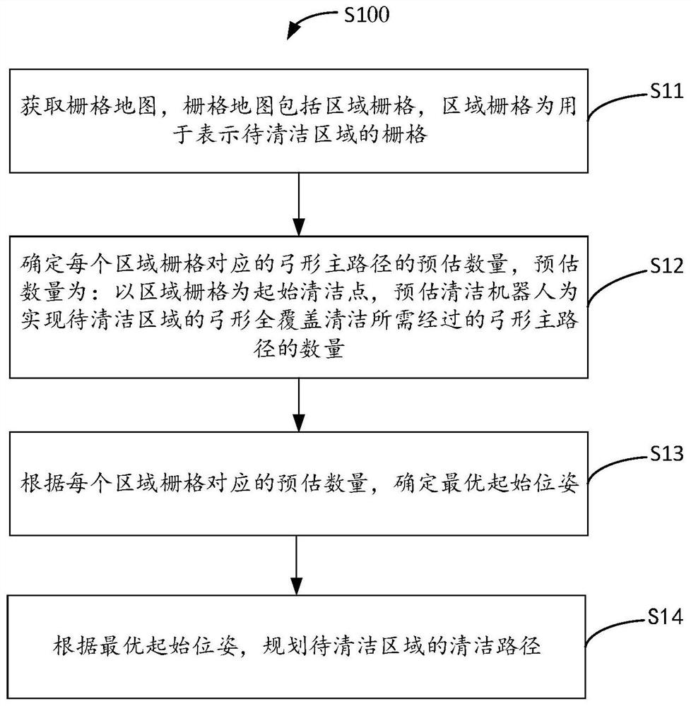
[0035] figure 1 It shows a schematic flowchart of a path planning method provided by an embodiment of the present invention. As an example but not a limitation, the path planning method can be applied to a cleaning robot. The path planning method is described in detail as follows. The path planning method S100 includes :
[0036] S11. Obtain a grid map. The grid map includes an area grid, and the area grid is a grid used to represent an area to be cleaned.
[0037] As an example and not limitation, the grid map is generated based on the environment image corresponding to the target space, the target space includes the space where the cleaning robot is currently located, for example, the target space is an overall indoor space, and the overall indoor space includes Each room is, for example, a bedroom, a kitchen, or a living room. Correspondingly, the area map indicated by the grid map includes a bedroom map, a kitchen map, or a living room map. For another example, the target...
Embodiment 2
[0162] see Figure 7 , Figure 7 A schematic diagram of the circuit structure of a cleaning robot provided in an embodiment of the present invention, wherein the cleaning robot in the embodiment of the present invention can be configured in any suitable shape in order to achieve a specific business function operation, for example, in some embodiments, the cleaning robot Including but not limited to sweeping robots, vacuuming robots, mopping robots, and scrubbing robots, etc.
[0163] Such as Figure 7 As shown, the cleaning robot 700 includes one or more processors 71 and memory 72 . in, Figure 7 A processor 71 is taken as an example.
[0164] Processor 71 and memory 72 can be connected by bus or other means, Figure 7 Take connection via bus as an example.
[0165] The memory 72, as a non-volatile computer-readable storage medium, can be used to store non-volatile software programs, non-volatile computer-executable programs and modules, such as program instructions cor...
PUM
 Abstract
Description
Claims
Application Information