Epoxy resin filter with filter core convenient to replace

A technology for replacing epoxy resin and filter elements, which is applied in the directions of magnetic separation, solid separation, chemical instruments and methods, etc., can solve the problems of reducing the filtration efficiency of epoxy resin and wasting working time, so as to improve the filtration effect, improve work efficiency, The effect of increasing work output

Pending Publication Date: 2021-08-10
屠南
View PDF8 Cites 0 Cited by
  • Summary
  • Abstract
  • Description
  • Claims
  • Application Information

AI Technical Summary

Problems solved by technology

[0005] In order to overcome the disadvantages of stopping the machine after a long period of filtration and disassembling the machine to replace the filter element, this replacement method requires a large number of workers to participate, which not only wastes working time, but a

Method used


Image

  • Epoxy resin filter with filter core convenient to replace
  • Epoxy resin filter with filter core convenient to replace
  • Epoxy resin filter with filter core convenient to replace

Examples


Embodiment 1

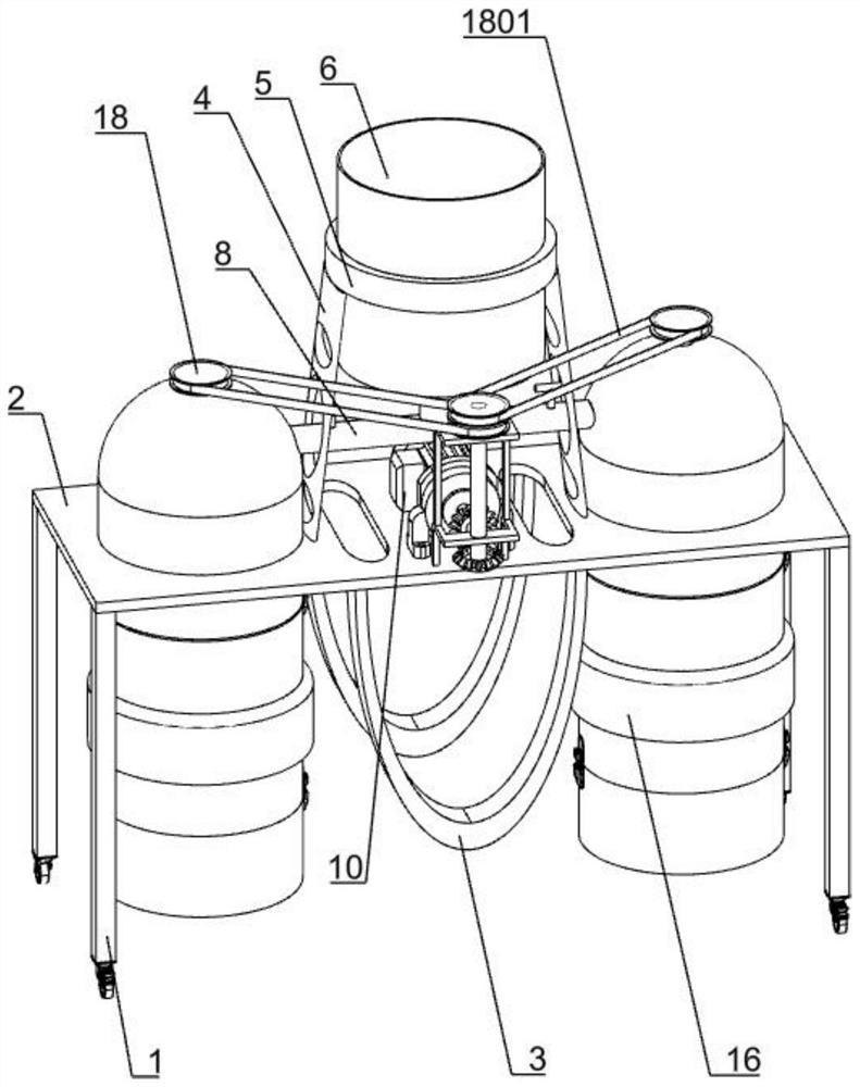
[0034] Such as figure 1As shown, it includes a support leg 1, a rectangular plate 2, a U-shaped frame 3, a blanking assembly, a power assembly, a filter assembly and a stirring assembly. There are four support legs 1, and the rectangular plate 2 is fixedly installed on the top of the four support legs 1. , there are two U-shaped frames 3, the two U-shaped frames 3 are fixedly installed on the lower side of the rectangular plate 2, the two U-shaped frames 3 are located in the middle of the rectangular plate 2, and the blanking assembly is fixedly installed on the upper side of the rectangular plate 2, and the power The assembly is fixedly installed on the upper side of the rectangular plate 2, the power assembly is on the lower side of the blanking assembly, the filter assembly is installed on the rectangular plate 2, the filter assembly is on both sides of the blanking assembly and the power assembly, and the stirring assembly is installed inside the filter assembly.

[0035] ...

Embodiment 2

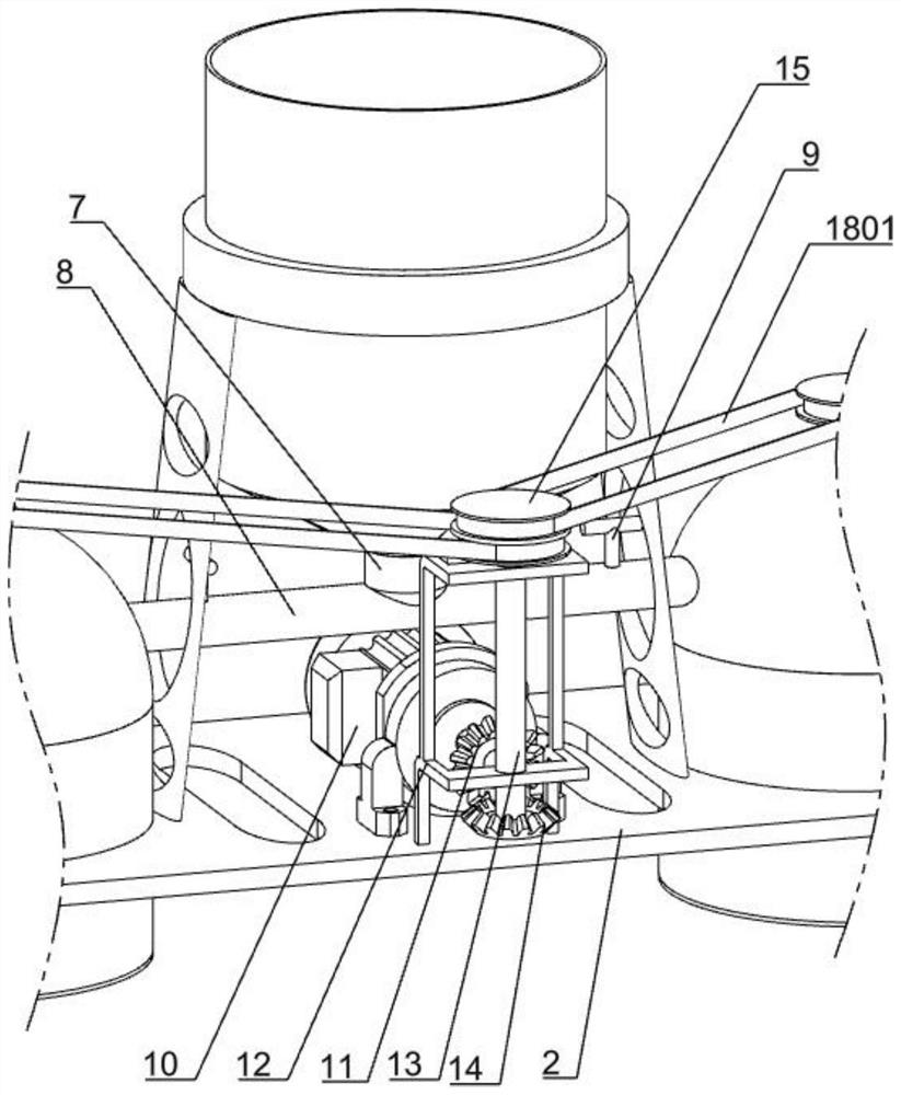
[0037] Such as figure 1 As shown, the blanking assembly includes a support plate 4, a cylindrical frame 5, a barrel 6, a short tube 7, a long tube 8 and a switch 9. There are two support plates 4, and the two support plates 4 are symmetrically installed on the rectangular plate 2. On the upper side, a cylindrical frame 5 is fixedly installed on the top of the two support plates 4, and the barrel 6 is fixedly installed inside the cylindrical frame 5. The bottom end of the barrel 6 is fixedly installed with a short tube 7, and the bottom end of the short tube 7 is fixedly installed Long pipe 8 is arranged, and long pipe 8 communicates with barrel 6 by short pipe 7, and switch 9 is all installed at the two ends of long pipe 8.

[0038] The support plate 4 plays the role of supporting the cylindrical frame 5, and the cylindrical frame 5 plays the role of installing the barrel 6. When using this device, pour epoxy resin into the barrel 6, and put one of the switches 9 on the long t...

Embodiment 3

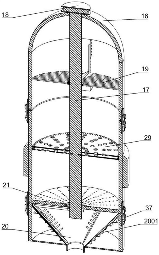
[0046] Such as Figure 9 Shown, also comprise rectangular column 25, slide bar 26, the 4th spring 27 and small cylinder 28, all are fixedly installed with rectangular column 25 on the outside of each stirring paddle 24, all have rectangular groove on each rectangular column 25, many A slide bar 26 is slidably installed in the rectangular groove on each rectangular column 25, and the top of the slide bar 26 is in contact with the filter barrel 16, and a fourth spring 27 is installed in the rectangular groove on each rectangular column 25, and the fourth spring 27 Between the lower side of the slide bar 26 and the bottom end of the rectangular column 25 , a plurality of small cylinders 28 are installed on the outside of each rectangular column 25 and the slide bar 26 .

[0047] When the stirring paddle 24 moves, it will drive the rectangular column 25 to move. When the stirring paddle 24 moves, the rectangular column 25 will move up and down. Slide down, when the rectangular co...


PUM


Abstract

The invention discloses an epoxy resin filter with a filter core convenient to replace. The technical problem to be solved is to provide an epoxy resin filter with a filter core convenient to replace, wherein the epoxy resin filter can continuously filter an epoxy resin during replacement, and can improve the production capacity while reducing manual participation. According to the technical scheme, the epoxy resin filter with the filter core convenient to replace comprises supporting legs, a rectangular plate and U-shaped frames, wherein the number of the supporting legs is four, the rectangular plate is fixedly installed at the top ends of the four supporting legs, the number of the U-shaped frames is two, the two U-shaped frames are fixedly installed on one side of the rectangular plate, and the two U-shaped frames are located in the middle of the rectangular plate. According to the invention, two filter barrels are arranged, one filter barrel is used for filtering each time, and when an overheated filter screen needs to be replaced after filtering for a period of time, the other filter barrel can be opened for filtering, so that the working efficiency is obviously improved, and the working yield is increased.

Description

technical field [0001] The invention relates to an epoxy resin filter, in particular to an epoxy resin filter which is easy to replace the filter element. Background technique [0002] Resin usually refers to a softening or melting range after being heated. When softening, it has a tendency to flow under the action of an external force. It is solid, semi-solid, and sometimes liquid organic polymers at room temperature. In a broad sense, it can be processed as plastic products. Any high molecular compound of raw material is called resin. [0003] At present, the machine for filtering epoxy resin needs to stop the machine after filtering for a long time, and disassemble the machine to replace the filter element. This replacement method requires a large number of workers to participate, which not only wastes working time, but also reduces Filtration efficiency of epoxy resin. [0004] Therefore, be necessary for the shortcoming of prior art, design a kind of easy to replace f...

Claims


Application Information

Patent Timeline
IPC IPC(8): B03C1/30B29B13/10
CPCB03C1/30B29B13/10
Inventor 屠南
Owner 屠南
Why Eureka
Try Eureka