
Impeller blade robot trajectory constant force tracking deburring method

An impeller blade and robot technology, which is used in manipulators, grinding machine parts, program-controlled manipulators, etc., can solve the problems of large structure size, narrow blade working space, uncontrollable floating accuracy, etc., and achieves strong self-adaptation and high flexibility. , to avoid the effect of reducing the processing quality

Active Publication Date: 2021-09-21
NANJING UNIV OF AERONAUTICS & ASTRONAUTICS
View PDF3 Cites 0 Cited by
  • Summary
  • Abstract
  • Description
  • Claims
  • Application Information

AI Technical Summary

Problems solved by technology

The burrs on the blade surface can easily lead to problems such as surface cracking and edge trimming, and its processing quality directly affects the accuracy and shape accuracy of instant noodles. Research on a processing method and equipment that can be applied to impeller blades with weak rigidity, complex curved surfaces, and narrow spaces for deburring. It has very important practical value to promote the development of high-performance engines in China
[0003] Most of the existing blade deburring methods and equipment are aimed at a single blade, and there are few studies on the grinding and polishing of engine impeller blades. The working space between the blades is narrow, and the processing attitude of traditional grinding and polishing methods such as belt machines and grinders is fixed. , Large structural size, uncontrollable floating precision, and impeller blades with poor processing space openness are prone to interference, causing processing damage to the blades
When using a fixed curvature belt machine and a grinder to process variable curvature impeller blades at the same time, when the curvature of the impeller blade is smaller than that of the belt machine / grinder, there will be a situation where it cannot be processed

Method used


Image

  • Impeller blade robot trajectory constant force tracking deburring method
  • Impeller blade robot trajectory constant force tracking deburring method
  • Impeller blade robot trajectory constant force tracking deburring method

Examples


Embodiment Construction

[0037] In the following description, numerous specific details are given in order to provide a more thorough understanding of the present invention. It will be apparent, however, to one skilled in the art that the present invention may be practiced without one or more of these details. In other examples, some technical features known in the art are not described in order to avoid confusion with the present invention.

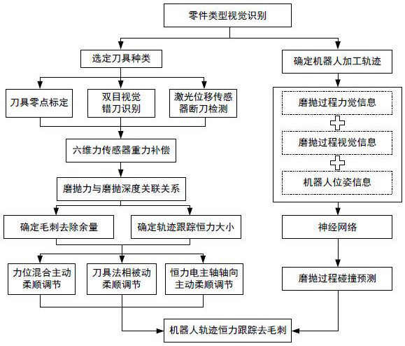
[0038] The applicant believes that the complex spatial surface and weak rigidity of the impeller blades are important reasons for its poor deburring consistency. Force sensor data, and constantly adjust the fit of the grinding trajectory, combine the BP neural network to train the data set, and apply the trained model to the sensorless industrial robot grinding instance, and achieve constant force grinding according to the preset grinding force threshold . In the above-mentioned patent scheme, the sensorless trajectory constant force tracking grinding is reali...


PUM


Abstract

The invention relates to a deburring method for impeller blade robot trajectory constant force tracking. The method is based on the grinding and polishing trajectory of part type identification and the independent selection of deburring tools, and innovates the tool information integrating tool zero point calibration, wrong tool identification and broken tool detection. The guarantee system establishes the relationship between the amount of burr removal and the normal force of grinding and polishing, and integrates the passive adjustment of the normal direction of the tool, the axial floating of the constant force electric spindle and the active and compliant control of the mixed force and position, and the constant force tracking of the robot grinding and polishing trajectory. The collision prediction of grinding and polishing is realized by neural network learning of vision, force sense and robot pose information. The method of the invention provides a solution for the deburring processing of parts with complex curved surfaces and narrow spaces, has the characteristics of strong self-adaptation, high flexibility, etc., realizes constant force tracking of robot deburring tracks through multi-source information fusion, and has good practicability and versatility.

Description

technical field [0001] The invention relates to the field of G05D: non-electric variable control or regulation system, and specifically relates to a deburring method for impeller blade robot track constant force tracking. Background technique [0002] As the "heart" of aircraft, aero-engines have received attention from all over the world in their manufacturing technology. The impeller blade is the core component of an aero-engine, and its manufacturing precision is directly related to the overall performance of the engine. Usually, in order to improve the propulsion performance of the engine, the design and manufacture of its blades must meet the requirements of fluid dynamics. Therefore, the surface shape of the blades is mostly free-form surfaces that are stacked arbitrarily in space, which poses a high challenge to the processing of parts. The burrs on the blade surface can easily lead to problems such as surface cracking and edge trimming, and its processing quality di...

Claims


Application Information

Patent Timeline
Patent Type & Authority Patents(China)
IPC IPC(8): B24B9/04B24B49/16B24B41/06B24B49/12B24B47/20B25J11/00B25J9/16
CPCB24B9/04B24B41/06B24B47/20B24B49/12B24B49/165B25J9/1664B25J11/0065
Inventor 田威王品章王长瑞张新龙张奇沈烨刘明轩康瑞浩
Owner NANJING UNIV OF AERONAUTICS & ASTRONAUTICS
Learn More