Sludge treatment device based on hydraulic engineering

A technology for sludge treatment and water conservancy engineering, applied in the direction of water/sludge/sewage treatment, sludge treatment, chemical instruments and methods, etc., can solve problems such as low efficiency, slow sewage circulation, and inability to effectively solve the problem of sludge purification, reaching Avoid rust and wear, and achieve the effect of sealing

Pending Publication Date: 2021-08-10
魏国奇
View PDF6 Cites 0 Cited by
  • Summary
  • Abstract
  • Description
  • Claims
  • Application Information

AI Technical Summary

Problems solved by technology

[0002] Water conservancy engineering is a project built to control and allocate natural surface water and groundwater to achieve the purpose of eliminating harm and rejuvenating profits. It is also called water engineering. Water is an indispensable and precious resource for human production and life, but its natural existence The state does not fully meet the needs of human beings. Only by building water conservancy projects can water flow be controlled, floods prevented, and water volume adjusted and distributed to meet the needs of people's life and production for water resources. Water conservancy projects include silt treatment projects. Some sludge treatment devices are inefficient during the sludge treatment process, and the sludge cannot be discharged in time, resulting in sludge blockage and slow sewage flow. Not only that, the existing sludge treatment equipment cannot effectively purify and filter the sludge, resulting in the inability to effectively solve the problem of sludge. Purification problem, so a new method is urgently needed to solve such a problem

Method used


Image

  • Sludge treatment device based on hydraulic engineering
  • Sludge treatment device based on hydraulic engineering
  • Sludge treatment device based on hydraulic engineering

Examples


Embodiment Construction

[0018] The preferred examples of the present invention will be described below in conjunction with the accompanying drawings. It should be understood that the preferred examples described here are only used to illustrate and explain the present invention, and are not intended to limit the present invention.

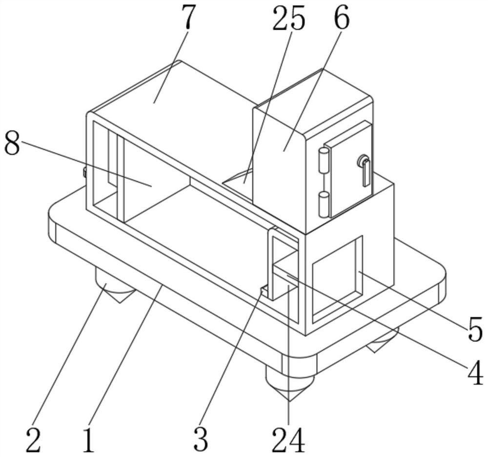
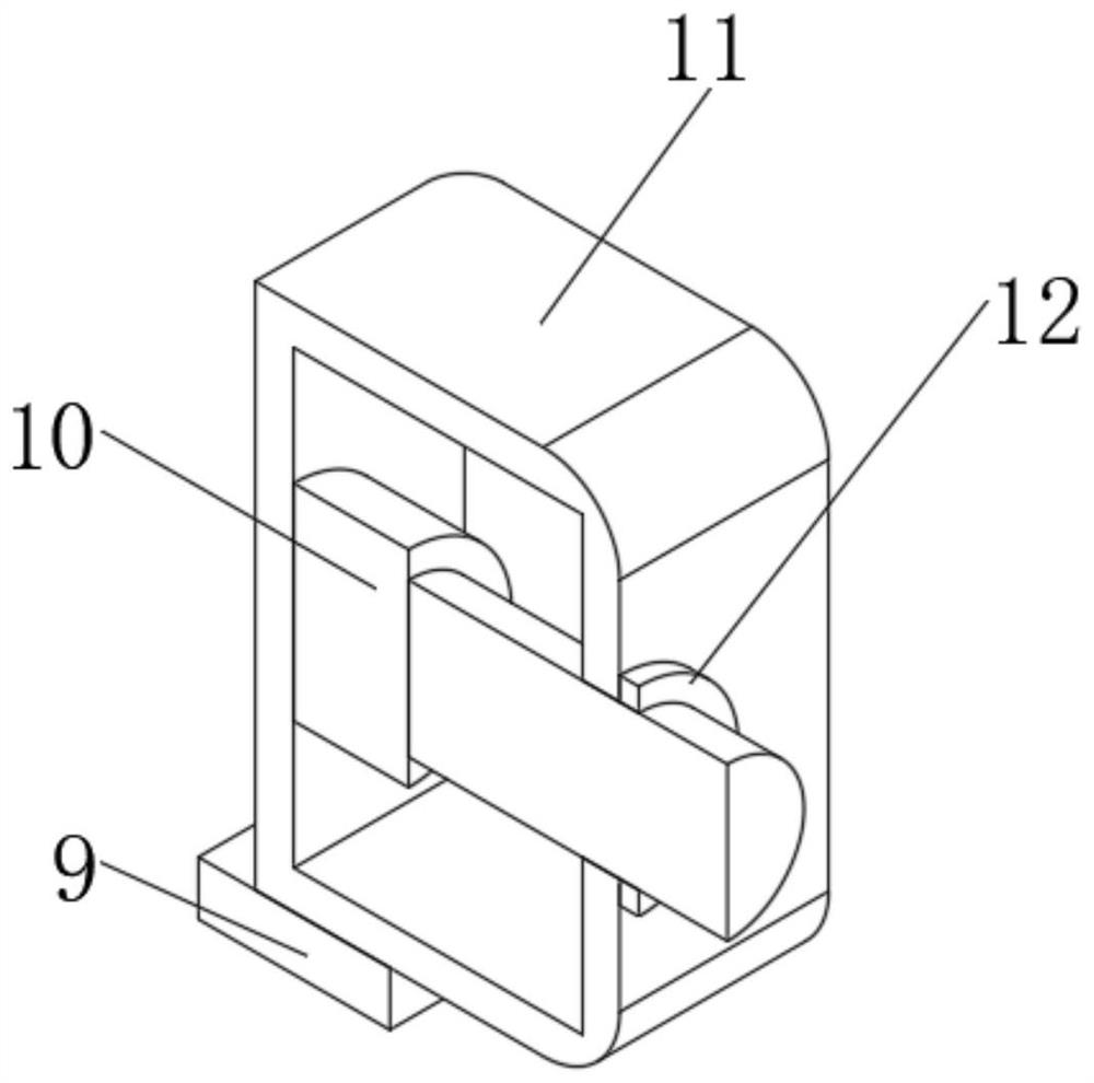
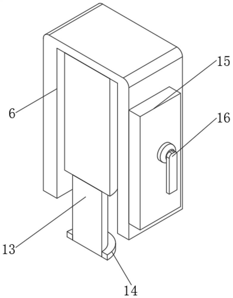
[0019] Such as Figures 1 to 5 As shown, this kind of sludge treatment device based on water conservancy project can be fixed on the bottom surface of the river by setting the fixed pile 2, so as to realize the purpose of fixing the device and play the role of stabilizing the device. 10 and the push plate 8 can cooperate with the telescopic rod 13, the blocking plate 24 and the push port 5 to discharge the silt inside the treatment box 7, and play the role of quickly removing the silt, so as to avoid that the silt inside the treatment box 7 cannot be removed in time, resulting in silt The problem of excessive clogging caused by the first filter plate 17 and the second fil...


PUM


Abstract

The invention relates to the technical field of hydraulic engineering,and especially relates to a sludge treatment device based on hydraulic engineering. The device comprises a base, two groups of fixing piles are fixedly connected to the bottom surface of the base, a treatment box is fixedly connected to the upper surface of the base, and a fixing through hole is formed in the left side surface of the treatment box. A hydraulic box is clamped in the fixing through hole, a hydraulic rod is fixedly connected to the inner side wall of the hydraulic box, and the output end of the hydraulic rod penetrates through the hydraulic box and extends to the right side of the hydraulic box.By arranging the fixing piles, the device can be fixed on the bottom face of a river channel, the purpose of fixing the device is achieved, and the effect of stabilizing the device is achieved. By arranging the hydraulic rod and a push plate, the hydraulic rod and the push plate can be matched with a telescopic rod, a plugging plate and a push opening, sludge in the treatment box can be discharged, the effect of rapidly discharging the sludge is achieved, and the problem that the sludge in the treatment box cannot be discharged in time, and consequently blockage is caused by excessive sludge is solved.

Description

technical field [0001] The invention relates to the technical field of water conservancy engineering, in particular to a sludge treatment device based on water conservancy engineering. Background technique [0002] Water conservancy engineering is a project built to control and allocate natural surface water and groundwater to achieve the purpose of eliminating harm and rejuvenating profits. It is also called water engineering. Water is an indispensable and precious resource for human production and life, but its natural existence The state does not fully meet the needs of human beings. Only by building water conservancy projects can water flow be controlled, floods prevented, and water volume adjusted and distributed to meet the needs of people's life and production for water resources. Water conservancy projects include silt treatment projects. Some sludge treatment devices are inefficient during the sludge treatment process, and the sludge cannot be discharged in time, re...

Claims


Application Information

Patent Timeline
Patent Type & Authority Applications(China)
IPC IPC(8): C02F11/121
CPCC02F11/121
Inventor 魏国奇甘素琴张瑞张子博张冰
Owner 魏国奇
Why Eureka
Try Eureka