Friction energy dissipation supporting structure, assembly type supporting frame system and construction method
A friction energy dissipation and support structure technology, applied in building components, building structures, protective buildings/shelters, etc., can solve the problems of frame structure damage and loss of bearing capacity, etc.
- Summary
- Abstract
- Description
- Claims
- Application Information
AI Technical Summary
Problems solved by technology
Method used
Image
Examples
Embodiment 1
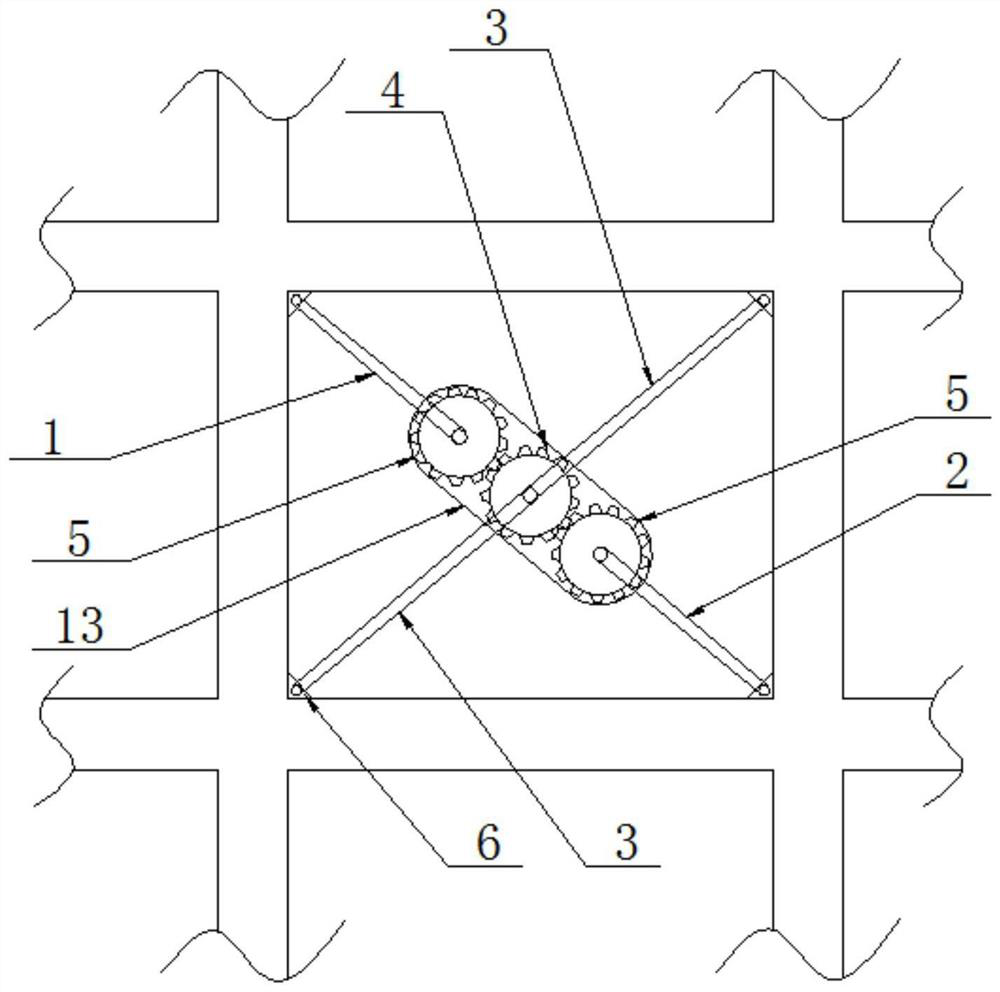
[0035] Please refer to figure 1 The schematic structural diagram of the first embodiment of a frictional energy dissipation support structure provided by the application is shown, including: an energy dissipation gear assembly and a first support rod 1 and a second support rod connected to the energy dissipation gear assembly 2 and two third support rods 3;
[0036] The energy-consuming gear assembly includes: a first gear 4 and two second gears 5 meshed with each other; the first gear 4 is located between the two second gears 5; the first gear 4 and the two The third support rod 3 is connected, and the two third support rods 3 are arranged diagonally in the frame; one of the second gear 5 is connected with the first support rod 1, and the other of the second gear 5 Connect with the second support rod 2;
[0037] The free ends of the first support rod 1 , the second support rod 2 and the third support rod 3 are all hinged with connecting hinges 6 , which are installed at the...
Embodiment 2
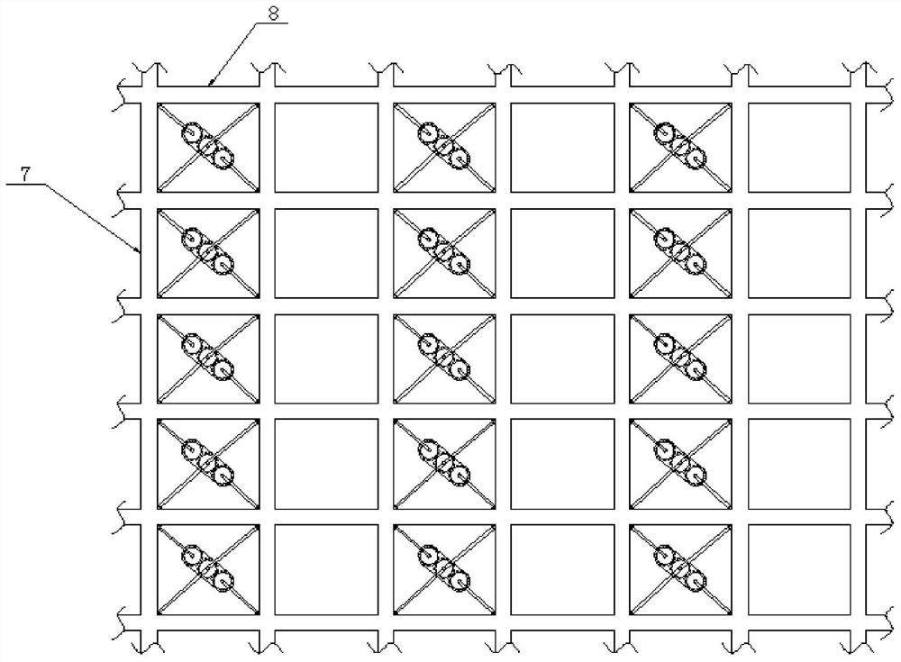
[0050] Such as figure 2 As shown, an assembled support frame system includes: prefabricated columns 7, prefabricated beams 8 and the above-mentioned frictional energy dissipation support structure arranged in the frame formed by the prefabricated columns 7 and the prefabricated beams 8;
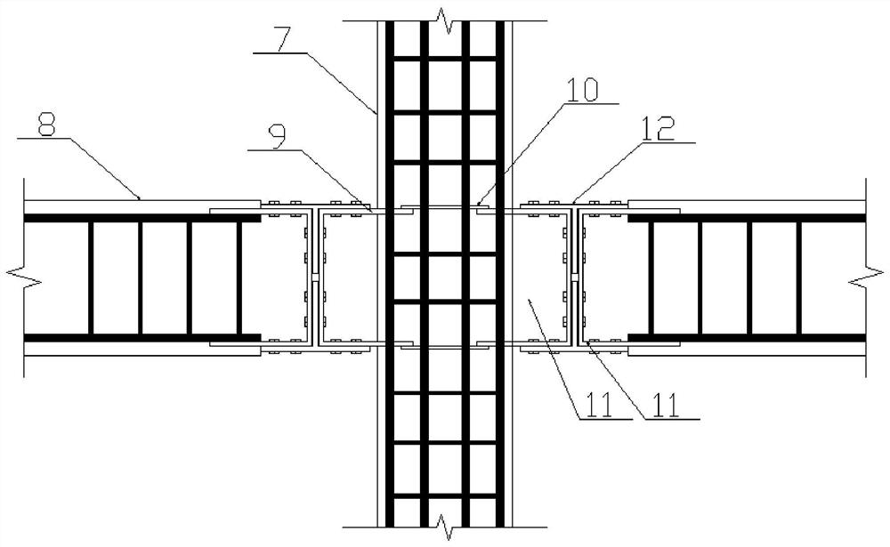
[0051] The skeleton of the prefabricated column 7 is the first channel steel 9 oppositely arranged in two opening directions, and the flanges of the two two are respectively connected by connecting plates 10; the skeleton of the prefabricated beam 8 is the second channel steel 11, and Its web is arranged adjacent to the web of the first channel steel 9; a T-shaped steel 12 is arranged between the first channel steel 9 and the second channel steel 11, and the flanges of the T-shaped steel 12 are respectively It is connected with the flange on the same side of the first channel steel 9 and the second channel steel 11, and the web of the T-shaped steel 12 is connected with the web of the first ...
Embodiment 3
[0062] A construction method based on the above-mentioned prefabricated support frame system, comprising the following steps:
[0063] Step S1: the prefabricated columns 7 and prefabricated beams 8 are processed and formed in the factory;
[0064] Step S2: Assembling the prefabricated columns 7 and prefabricated beams 8 on site using bolts;
[0065] Step S3: Install the connecting hinge 6 at the corner of the frame formed by the prefabricated column 7 and the prefabricated beam 8;
[0066] Step S4: Connect the first support rod 1 and the second support rod 2 with the two second gears 5 respectively, and connect the two third support rods 3 with the first gear 4;
[0067] Step S5: Hinge the first support rod 1 , the second support rod 2 and the two third support rods 3 with the four connecting hinges 6 respectively.
[0068] In this embodiment, in step S1, the prefabricated column 7 and the prefabricated beam 8 are processed and shaped by the factory;
[0069] Specifically, ...
PUM
 Abstract
Description
Claims
Application Information
 - R&D
- Intellectual Property
- Life Sciences
- Materials
- Tech Scout
- Unparalleled Data Quality
- Higher Quality Content
- 60% Fewer Hallucinations
Browse by: Latest US Patents, China's latest patents, Technical Efficacy Thesaurus, Application Domain, Technology Topic, Popular Technical Reports.
© 2025 PatSnap. All rights reserved.Legal|Privacy policy|Modern Slavery Act Transparency Statement|Sitemap|About US| Contact US: help@patsnap.com


