An engine balance system test platform device

A technology for balancing systems and test platforms, applied to engine components, machines/engines, mechanical equipment, etc., can solve problems that affect production efficiency, take up a lot of time and energy, and are difficult to disassemble and replace

Active Publication Date: 2022-02-15
YANGZHOU UNIV
View PDF17 Cites 0 Cited by
  • Summary
  • Abstract
  • Description
  • Claims
  • Application Information

AI Technical Summary

Problems solved by technology

In the gear manufacturing industry, since most of the gears and shafts in the automotive industry adopt interference or transitional assembly, assembly line assembly, and the gears are closely arranged inside and outside, if abnormal noise is found during the test run, find out the burr in the gear set It is very difficult to disassemble and replace gears, which will take up a lot of time and energy and seriously affect production efficiency; at the same time, in the application stage of gears, the gear chamber is an important part of the car engine

Method used


Image

  • An engine balance system test platform device
  • An engine balance system test platform device
  • An engine balance system test platform device

Examples


Embodiment 1

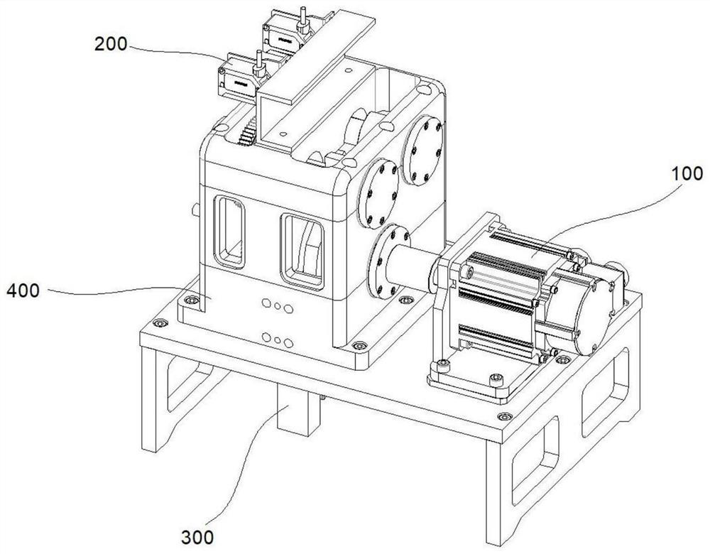
[0033] refer to figure 1 , 2 , provides a schematic diagram of the overall structure of the engine balance system test platform device, including a rotary assembly 100, the rotary assembly 100 includes a motor part 101 and an output shaft part 102 connected to the motor part 101 and extending outwards, and a motor part 101- The eccentric part 103 on the side; the detection assembly 200, the detection assembly 200 includes the sensor part 201 arranged on the device main body 400 and the gear part 202 connected with the rotary assembly 100 and the support part 203 arranged inside the device main body 400, the gear part 202 arranged on the support member 203 ; and, the balance assembly 300 , the balance assembly 300 is arranged on the lower side of the device main body 400 and includes a conduction member 301 and a slider member 302 .

[0034] Specifically, the main structure of the present invention includes a rotary assembly 100, a detection assembly 200 and a balance assembly...

Embodiment 2

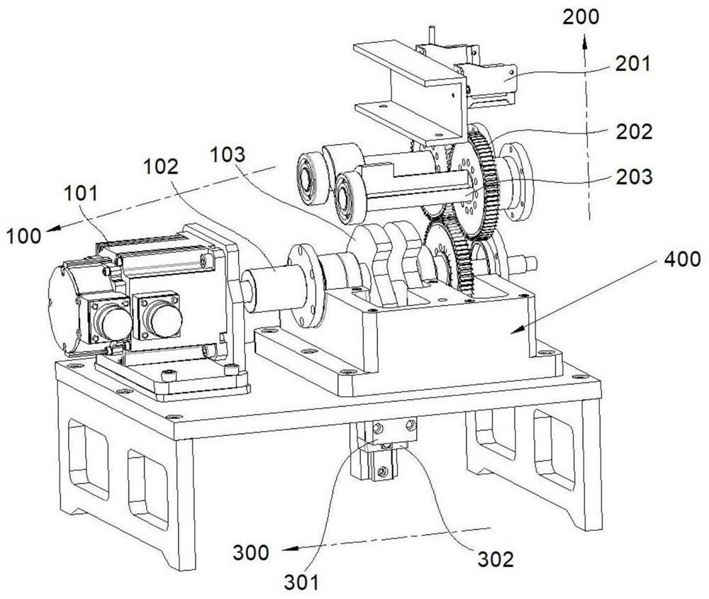
[0039] refer to image 3 and Figure 4 , this embodiment is different from the first embodiment in that: the device main body 400 includes a mounting platform 401 and a casing 402 , and the casing 402 is set on the mounting platform 401 . The motor component 102 includes a motor 101a and a motor fixing frame 102b, the motor 102a is arranged on the upper side of the motor fixing frame 102b, and the motor fixing frame 102b is arranged on the installation platform 401 . The eccentric wheel member 103 passes through the output shaft member 102 , the lower side of the eccentric wheel member 103 is connected to the conducting member 301 , and one end thereof is connected to the gear member 202 .

[0040] The conduction member 301 includes a crank 301 a and a connection block 301 b, the crank 301 a is rotatably connected to the connection block 301 b, and the crank 301 a is rotatably connected to the eccentric wheel member 103 . The slider component 302 includes a slide rail 302a a...

Embodiment 3

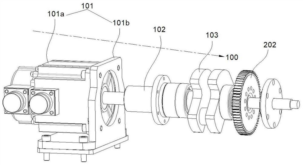
[0046] refer to Figure 5 , This embodiment is different from the above embodiments in that: the sensor part 201 is arranged on the upper side of the gear part 202, including a sensor 201a and a sensor support frame 201b, the sensor 201a is arranged on the upper side of the sensor support frame 201b, and the sensor support frame 201b is installed on the shell 402 Upper. The gear part 202 includes a transmission gear 202a and a detection gear 202b, the transmission gear 202a is connected with the output shaft part 102, and the detection gear 202b is matedly connected with the transmission gear 202a. The supporting component 203 is arranged inside the casing 402, and includes a supporting shaft 203a and a bearing 203b arranged outside the supporting shaft 203a, and the supporting shaft 203a is matedly connected with the detection gear 202b.

[0047] Specifically, in this embodiment, the sensor part 201 is arranged on the upper side of the gear part 202, including a sensor 201a ...


PUM


Abstract

The invention discloses an engine balance system test platform device. In the invention, a rotary assembly is arranged in the main body of the device, and a motor part is arranged inside the rotary assembly. The operation of the motor part drives the output shaft part to run at high speed, and the output shaft part is connected to the eccentric wheel part. When rotating, the eccentric wheel part drives the slider part to move up and down through the conductive part. When the conductive part rotates, a moment of inertia will be generated, and the moment of inertia will be balanced by the slider part to simulate the working state of the engine. On the other hand, the eccentric wheel part drives the rear gear part to rotate, and the gear part will generate vibration displacement and noise when it rotates at high speed. The noise and vibration displacement are collected and recorded by the sensor part. After summarization, through analysis, the comparison of different vibration noise amplitudes It can be seen that the structure of different gears is good or bad.

Description

technical field [0001] The invention relates to the technical field of equipment detection, in particular to an engine balance system test platform device. Background technique [0002] In the industrial society of the 21st century, industries such as general machinery and automobiles are prospering day by day, and the gears widely used in these industries have also entered the era of mass production. In the gear manufacturing industry, since most of the gears and shafts in the automotive industry adopt interference or transitional assembly, assembly line assembly, and the gears are closely arranged inside and outside, if abnormal noise is found during the test run, find out the burrs in the gear set It is very difficult to disassemble and replace gears, which will take a lot of time and energy, and seriously affect production efficiency; at the same time, in the application stage of gears, the gear chamber is an important part of the car engine. The function of the existin...

Claims


Application Information

Patent Timeline
Patent Type & Authority Patents(China)
IPC IPC(8): F02B77/08
CPCF02B77/08
Inventor 童任远龚俊杰刘子越韦源源
Owner YANGZHOU UNIV
Why Eureka
Try Eureka