A New Type of High Speed ​​Ball Bearing Cage

A technology for cages and ball bearings, which is applied in the field of new high-speed ball bearing cages, can solve the problems of bearing cage fracture failure, difficulty of lubricating oil entering, and increased heat generation of bearings, so as to improve service life, increase lubrication, Effect of reducing lubrication flow

Active Publication Date: 2021-11-09
BEIJING INSTITUTE OF TECHNOLOGYGY
View PDF10 Cites 0 Cited by
  • Summary
  • Abstract
  • Description
  • Claims
  • Application Information

AI Technical Summary

Problems solved by technology

With the continuous increase of the speed, the bearing cage is prone to fracture and failure, and the high speed will cause the heat generation of the bearing to increase, the temperature rise will increase, and the heat dissipation energy consumption will increase.
In addition, for bearings that use oil injection lubrication, at high speeds, an air curtain effect will occur in the bearing cavity, making it difficult for lubricating oil to enter the bearing cavity, causing the bearing to fail due to lack of lubrication
It is difficult to install the two-piece riveted cage, while the one-piece crown cage is installed asymmetrically in the bearing, making it unstable during operation and prone to breakage at the root of the cage

Method used


Image

  • A New Type of High Speed ​​Ball Bearing Cage
  • A New Type of High Speed ​​Ball Bearing Cage
  • A New Type of High Speed ​​Ball Bearing Cage

Examples


Embodiment Construction

[0029] The following will clearly and completely describe the technical solutions in the embodiments of the present invention with reference to the accompanying drawings in the embodiments of the present invention. Obviously, the described embodiments are only some, not all, embodiments of the present invention. Based on the embodiments of the present invention, all other embodiments obtained by persons of ordinary skill in the art without making creative efforts belong to the protection scope of the present invention.

[0030] In order to make the above objects, features and advantages of the present invention more comprehensible, the present invention will be further described in detail below in conjunction with the accompanying drawings and specific embodiments.

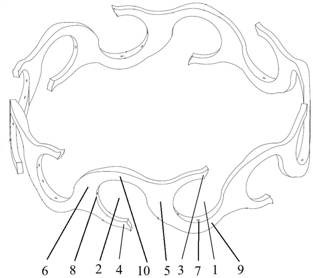
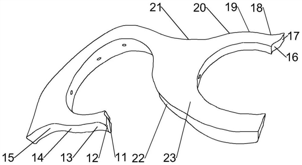
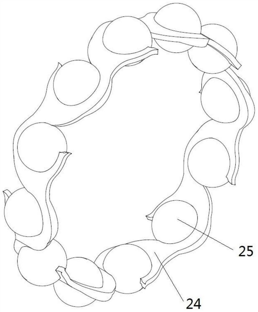
[0031] refer to Figure 1-3 As shown, the present invention provides a new type of high-speed ball bearing cage, including: several cage bodies 24, several rolling elements 25, flow guide parts, lubricating parts ...


PUM


Abstract

The invention provides a new type of high-speed ball bearing cage, including: several cage bodies, several rolling elements, flow guide parts, lubricating parts and reinforcement parts; wherein, each cage body is used to position the rolling bodies, so that The rolling elements rotate stably and reduce vibration. Each cage body half-wraps two rolling elements; several cage bodies are connected end-to-end in the circumferential direction; the flow guide part actively regulates the flow field through the cage body and guides the lubricating oil to the wear-prone area The guide part includes a first guide vane and a second guide vane arranged in contact with the rolling elements respectively; the lubricating part forms an oil film on the surface of the rolling elements to reduce the friction between the rolling elements and the cage body; the reinforcement part, It is used to strengthen the structural strength of the cage body and reduce the probability of fracture failure of the cage body. The invention can improve the strength of the cage, avoid fracture and failure, and facilitate lubrication and heat dissipation.

Description

technical field [0001] The invention belongs to the field of ball bearings, in particular to a novel high-speed ball bearing cage. Background technique [0002] Bearings are the core components of major equipment such as aero-engines, high-speed railways, and electric vehicles. Ball bearings generally consist of inner rings, outer rings, cages and rolling elements. The main function of the bearing cage is to evenly separate the rolling elements. If there is no bearing cage, the adjacent rolling elements will cause wear due to the large relative sliding speed at the contact point when they rotate. [0003] At present, bearing cages can be roughly divided into two-piece riveted cages and one-piece crown cages. With the continuous increase of the speed, the bearing cage is prone to fracture and failure, and the high speed will cause the heat generation of the bearing to increase, the temperature rise will increase, and the heat dissipation energy consumption will increase. ...

Claims


Application Information

Patent Timeline
Patent Type & Authority Patents(China)
IPC IPC(8): F16C33/38F16C33/42F16C33/66
CPCF16C33/38F16C33/425F16C33/6659F16C33/6681
Inventor 吴维韦春辉苑士华李鑫勇
Owner BEIJING INSTITUTE OF TECHNOLOGYGY
Why Eureka
Try Eureka