A multifunctional led light

A technology of LED lights and LED light strips, which is applied in lighting and heating equipment, fixed lighting devices, semiconductor devices of light-emitting elements, etc. Problems such as poor disassembly effect, to achieve the effect of increased reflection angle, flexible and convenient use, and reduced area

Active Publication Date: 2021-12-17
GUANGDONG JUNSHENG LIGHTING TECH CO LTD
View PDF6 Cites 1 Cited by
  • Summary
  • Abstract
  • Description
  • Claims
  • Application Information

AI Technical Summary

Problems solved by technology

[0004] The purpose of the present invention is to provide a multi-functional LED lamp to solve the problem of poor detachable effect and inconvenient replacement and maintenance of the lamp strip; there is a risk that the middle shell will fall off, which has a certain potential safety hazard; the problem of not being able to adjust the light Irradiated area, irradiated brightness, inconvenient use

Method used


Image

  • A multifunctional led light
  • A multifunctional led light
  • A multifunctional led light

Examples


Embodiment 1

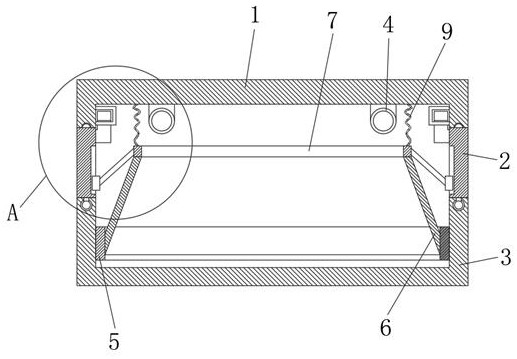
[0026] like figure 1 The multifunctional LED lamp shown includes an upper shell 1, a middle shell 2, a lower shell 3 and an annular LED light strip 4, the annular LED light strip 4 is installed on the inner top surface of the upper shell 1, and the annular LED light The belt 4 communicates with the circuit and the switch through wires. The middle casing 2 is detachably arranged on the bottom of the upper casing 1. The middle casing 2 is an annular plate. The top of the middle casing 2 is connected to the bottom of the upper casing 1. An engaging mechanism 11 is provided between the ends, and the lower housing 3 is rotatably arranged on the bottom end of the middle housing 2 , and the rotation axis of the lower housing 3 coincides with the center line of the middle housing 2 . Specifically, the bottom end of the side wall of the upper housing 1 is provided with a first annular chute, and the top end of the middle housing 2 is provided with an annular sliding bar 21. The cross s...

Embodiment 2

[0034] The difference between this embodiment and the first embodiment is:

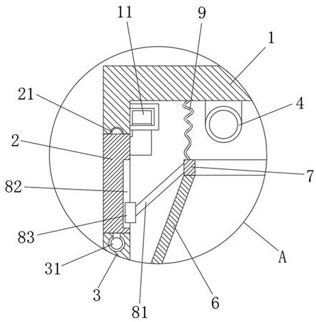
[0035] like Figure 4 As shown, the top of the first engaging member 111 is provided with a two-way telescopic piece 112, and the two-way telescopic piece 112 is distributed along the vertical direction. A reset member 117 is provided between the top of the first engaging member 111, wherein the reset member 117 is a rectangular coil spring, and the inner top surface and the inner bottom surface of the second engaging member 114 are provided with a second stopper 116, A blocking groove 115 is defined on the first blocking block 113 , and the second blocking block 116 can be engaged in the blocking groove 115 . Specifically, the side of the first stopper 113 away from the top of the first engaging member 111 has two slopes, and the transition between the two slopes is rounded. Above, the blocking groove 115 is a concave arc structure, and the second blocking block 116 adopts a hemispherical structure...


PUM


Abstract

The invention discloses a multifunctional LED lamp, which comprises an upper shell, a middle shell, a lower shell and an annular LED light strip, the annular LED light strip is installed on the inner top surface of the upper shell, and the middle shell The body is detachably arranged on the bottom end of the upper case, an engaging mechanism is provided between the top end of the middle case and the bottom end of the upper case, and the lower case is rotatably arranged at the bottom end of the middle case Above, the rotation axis of the lower casing coincides with the centerline of the middle casing. In the present invention, the middle housing is detachably installed on the bottom of the upper housing through the snap-fit ​​mechanism, which is convenient for replacement and maintenance of the ring-shaped LED light strip; the irradiation area can be adjusted by screwing the lower housing clockwise and counterclockwise. Irradiation brightness, more flexible and convenient to use; it can ensure that the annular ring, reflector and ring can move upward stably, allowing users to perform adjustment operations safely; effectively avoid the accidental fall of the middle shell.

Description

technical field [0001] The invention relates to the technical field of LED lamps, in particular to a multifunctional LED lamp. Background technique [0002] Ceiling lamps are a common type of lamps. The top surface is relatively flat. When installed, the top is completely attached to the roof. Common light sources include fluorescent lamps, tungsten halogen lamps, and LED lamps. Ceiling lamps are commonly used lamps in homes, offices, and entertainment venues. . The LED lamp is an electroluminescent semiconductor material chip, which is cured on the bracket with silver glue or white glue, and then connected to the chip and the circuit board with silver or gold wires, and sealed with epoxy resin around it to protect the inner core wire. Function, and finally install the shell, so the shock resistance of the LED lamp is good. [0003] The LED lights in the prior art have the following disadvantages: 1. The detachable effect is poor, and it is not convenient to replace and ma...

Claims


Application Information

Patent Timeline
Patent Type & Authority Patents(China)
IPC IPC(8): F21S8/04F21V15/01F21V19/00F21V17/12F21V7/00F21V14/04F21V17/10F21V17/16F21V7/28F21Y115/10
CPCF21S8/04F21V15/01F21V19/001F21V17/12F21V7/00F21V14/04F21V17/10F21V17/162F21V7/28F21Y2115/10
Inventor 杨吴蒙
Owner GUANGDONG JUNSHENG LIGHTING TECH CO LTD
Why Eureka
Try Eureka