
Impact fatigue test device

A test device and impact fatigue technology, applied in the direction of impact test, measurement device, machine/structural component testing, etc., can solve the problems of high cost, low cycle frequency, large space occupied by the test device, etc. Impact parameters, easily adjustable effects

Inactive Publication Date: 2021-08-10
TSINGHUA UNIV
View PDF17 Cites 4 Cited by
  • Summary
  • Abstract
  • Description
  • Claims
  • Application Information

AI Technical Summary

Problems solved by technology

[0004] However, it is found that in the above schemes, the use of pendulum or impact hammer to simulate cyclic impact often has a low cycle frequency, and the test device occupies a large space and costs high

Method used


Image

  • Impact fatigue test device
  • Impact fatigue test device
  • Impact fatigue test device

Examples


Embodiment

[0088] A clutch manufacturer needs to use Cr as the material in the sprag clutch 7 C 3 The coating (the substrate is bearing steel) is tested for impact fatigue resistance. The thickness of the coating is about 10 μm, and the required number of impact fatigue cycles needs to reach 10 5 more than times. The test device needs to meet the actual requirements of adjustable load range and impact energy, high efficiency and short test period. Select n=1400r / min, l 1 = 20mm, l 2 =145mm, r 1 = 30mm, r 2 =150mm, at this time the impact frequency is 4.65Hz, and it takes about 6 hours to complete a fatigue test. The thickness of the gasket can be adjusted between 0 and 20mm, and the impact speed can be adjusted between 0 and 0.5m / s; among them, Figure 6 It is a graph of the motion law of the slider.


PUM


Abstract

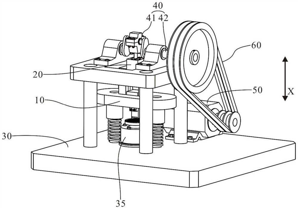
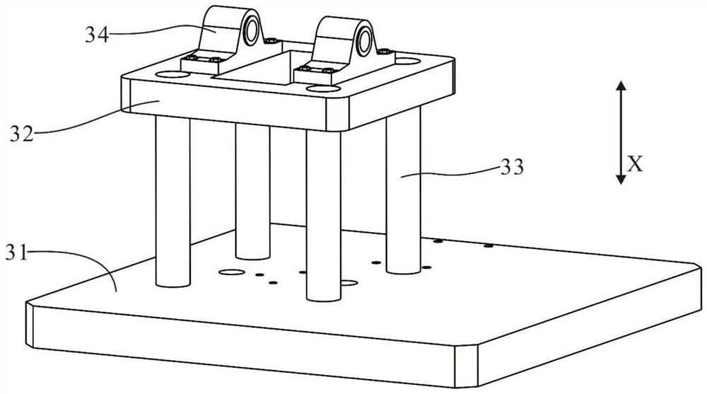
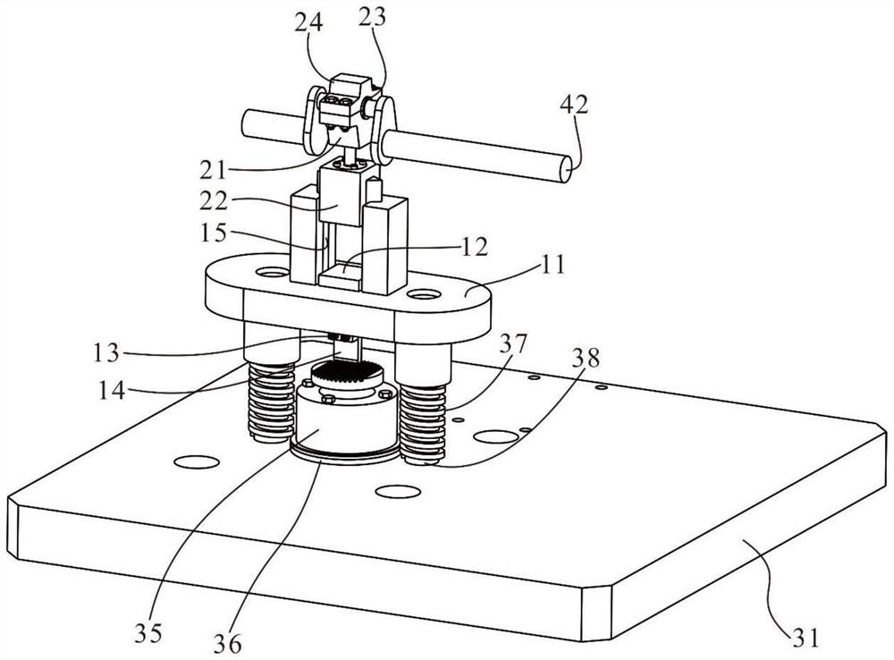
The invention discloses an impact fatigue test device which comprises a bearing unit, a first impact unit, a second impact unit and a crankshaft transmission unit which are sequentially arranged in a first direction. A bearing table of the bearing unit is used for placing a target object, the bearing unit is elastically connected with the first impact unit, and the first impact unit is in sliding connection with the second impact unit. Then one transmission shaft of the crankshaft transmission unit is inserted into the second impact unit, and the other transmission shaft of the crankshaft transmission unit is connected with a driving unit. Therefore, the impact fatigue test of the target object is completed, and the reliability of test data is improved. The technical problems that in an existing impact fatigue test device, due to the fact that an impact transmission mode based on a pendulum bob, an impact hammer, or the like is utilized, the impact cycle frequency is low, and the occupied space of the device is large are solved.

Description

technical field [0001] The invention relates to the technical field of testing devices, in particular to an impact fatigue testing device. Background technique [0002] In mechanical equipment, the parts and components on the equipment are often subject to cyclic shocks. For example, the vibration of the equipment itself during operation will cause cyclic shocks to the parts, or the interference of the environment where the equipment is located will also cause cyclic shocks to the parts. ; The cyclic impact often leads to fatigue damage of the parts, which in turn has a greater adverse effect on the performance of the equipment, and even leads to safety accidents in severe cases; thus, it is of great significance to obtain the impact fatigue resistance of the parts. [0003] In the prior art, in testing the impact fatigue resistance of components, an impact fatigue test device can usually be used. The impact fatigue test device simulates the cyclic impact effect by cyclicall...

Claims


Application Information

Patent Timeline
IPC IPC(8): G01M7/08G01N3/32G01N3/02
CPCG01M7/08G01N3/32G01N3/02
Inventor 田凌代菁洲郑孟蕾南哨克
Owner TSINGHUA UNIV
Learn More