A new energy vehicle battery explosion-proof flame retardant device

A new energy vehicle and battery technology, applied in the direction of batteries, electric vehicles, secondary batteries, etc., can solve the problems affecting passenger safety, combustion, explosion, etc., and achieve the effect of simplifying the operation of battery replacement and strong practicability

Active Publication Date: 2021-09-17
SHENZHEN JINZUN ENERGY TECH CO LTD
View PDF8 Cites 3 Cited by
  • Summary
  • Abstract
  • Description
  • Claims
  • Application Information

AI Technical Summary

Problems solved by technology

[0003] Most of the new energy vehicles now rely on the battery pack to drive the motor. While pure electrification brings quietness and environmental protection, there are also certain hidden dangers in the battery pack used by pure electricity. Explosion and combustion occur, which will affect the safety of passengers in the car. For this reason, we propose a new energy vehicle battery explosion-proof and flame-retardant device

Method used


Image

  • A new energy vehicle battery explosion-proof flame retardant device
  • A new energy vehicle battery explosion-proof flame retardant device
  • A new energy vehicle battery explosion-proof flame retardant device

Examples


Embodiment 1

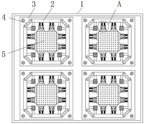
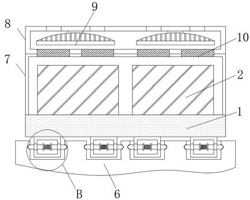
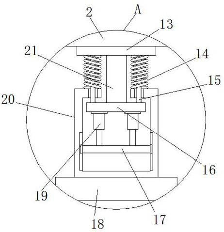
[0023] Embodiment 1: as Figure 1-Figure 5 As shown, a new energy vehicle battery explosion-proof and flame-retardant device proposed by the present invention includes an installation frame 1 and a chassis 6. The top of the installation frame 1 is fixed with four sets of mounting seats 3 by bolts, and the tops of the mounting seats 3 are placed with Battery 5, after the battery pack is hit, the surroundings of the battery 5 are initially supported by the fixed plate 2, and at the same time, the connecting rod 4 transfers the shaking of the fixed plate 2 to the rubber block inside the fixed plate 2 for the first buffer , eight connection blocks 18 are welded around the battery 5, and a third box 20 is welded on the side of the eight connection blocks 18 away from the battery 5, and the inner wall of the third box 20 is slidably connected with a movable plate 17, and the movable plate 17 is welded with two hydraulic rods 19 away from the side of the battery 5, and the end of the...

Embodiment 2

[0024] Embodiment 2: as Figure 1-Figure 5 As shown, the side of the fixed plate 13 away from the second movable column 21 is welded with the fixed plate 2, and the aftershocks that are not filtered by the fixed plate 2 will impact the fixed plate 13 and the connection from the inner side of the fixed plate 2 and the surroundings of the battery 5 respectively. On the block 18, the side of the fixed piece 13 away from the fixed plate 2 is welded with two first movable columns 15 that penetrate and extend into the third box body 20, and one end of the first movable column 15 located in the third box body 20 is Welded with the side of the movable block 16 away from the hydraulic rod 19, when the movable plate 17 slides to the limit of the chute, the hydraulic effect of the hydraulic rod 19 is transmitted to the movable plate 17 for support, and the fixed piece 13 is far away from the fixed plate 2 One side is all welded with the second movable column 21, and the other end of the ...

Embodiment 3

[0025] Embodiment 3: as Figure 1-Figure 5 As shown, the inner walls on both sides of the third box body 20 are provided with chute, and sliders are arranged in the chute, and the ends of the sliders that are close to each other are respectively welded to the two ends of the movable plate 17, and the cross section of the chute is T One end of the fixed plate 2 close to each other is hinged with a connecting rod 4, the side of the fixed plate 2 close to the battery 5 is welded with two steel bars, the end of the steel bar close to each other is welded with a rubber block, and the top of the chassis 6 is provided with four chamber, the inner walls on both sides of the chamber are provided with grooves, the tip of the protruding rod 23 is arc-shaped, and after the protruding rod 23 inside the fourth box body 22 touches the inner wall of the chamber, the protruding rod 23 The tip slides on the inner wall of the chamber, and the protruding rod 23 will be squeezed by the inner wall ...


PUM


Abstract

The invention discloses an explosion-proof and flame-retardant device for a new energy vehicle battery, which relates to the technical field of new energy vehicle battery packs. Aiming at the problems that the battery pack is prone to explosion and combustion after being collided, the following scheme is proposed, including an installation frame and a chassis. The top of the installation frame is fixed with four sets of mounting bases by bolts, and batteries are placed on the top of the mounting bases, and eight connecting blocks are welded around the battery, and the sides of the eight connecting blocks away from the battery are all welded There is a third box, the inner wall of the third box is slidably connected with a movable plate, and two hydraulic rods are welded on the side of the movable plate away from the battery. The invention has the effect of explosion-proof and flame-retardant for the battery pack, prevents the battery pack from easily exploding and igniting after violent vibration and collision, achieves effective shock absorption and fixing of the battery pack, and simplifies the operation of battery replacement at the same time. Strong, suitable for widespread promotion.

Description

technical field [0001] The invention relates to the technical field of battery packs of new energy vehicles, in particular to an explosion-proof and flame-retardant device for batteries of new energy vehicles. Background technique [0002] New energy vehicles in a broad sense, also known as alternative fuel vehicles, include pure electric vehicles, fuel cell electric vehicles and other vehicles that use non-petroleum fuels, as well as hybrid electric vehicles, ethanol gasoline vehicles and other vehicles that partially use non-petroleum fuels. All existing new energy vehicles are included in this concept, and are specifically divided into six categories: hybrid vehicles, pure electric vehicles, fuel cell vehicles, alcohol-ether fuel vehicles, natural gas vehicles, etc. New energy vehicles in the narrow sense can refer to the national " New Energy Automobile Manufacturing Enterprises and Product Access Management Regulations: New energy automobile refers to the use of unconve...

Claims


Application Information

Patent Timeline
Patent Type & Authority Patents(China)
IPC IPC(8): H01M50/242H01M50/204H01M50/244H01M50/249H01M50/258H01M50/264H01M10/613H01M10/625H01M10/6563B60L50/64A62C3/16A62C3/07
CPCA62C3/07A62C3/16B60L50/64H01M2220/20H01M10/613H01M10/625H01M10/6563Y02E60/10Y02T10/70
Inventor 卢婷婷
Owner SHENZHEN JINZUN ENERGY TECH CO LTD
Why Eureka
Try Eureka