Supercharge Your Innovation With Domain-Expert AI Agents!

Food processor with detachable crushing cutter assembly

A technology of a food processor and a crushing knife, which is applied in the field of food processing, can solve problems such as potential safety hazards, unreliable sealing of the crushing chamber, and easy leakage of the crushing chamber slurry, and achieve the effects of simplifying the positioning structure, improving reliability, and improving safety

Active Publication Date: 2021-08-13
JOYOUNG CO LTD
View PDF13 Cites 0 Cited by
  • Summary
  • Abstract
  • Description
  • Claims
  • Application Information

AI Technical Summary

Problems solved by technology

[0002]In the existing food processors, the pulverizer assembly is usually fixed to the bottom of the cup, which makes it difficult to clean the pulverizer assembly. Even with a cleaning brush, it is difficult to clean the pulverizer The cleaning dead angle under the component, so people design the crushing knife as a detachable structure with the cup body, for example, fix the crushing knife assembly on the cutter head, design the entire cutter head as a detachable structure with the cup body, or through a detachable The locking structure or the bottom cover of the cup seat detachably fix the crushing knife assembly on the cutter head. There are many detachable installation structures, but users usually cannot judge whether it is installed in place when installing, because the crushing knife assembly is installed in the crushing chamber. , When the pulverizer rotates, the pulverizer assembly vibrates greatly. If it is not installed in place, it will easily lead to unreliable sealing of the pulverization chamber, and the slurry in the pulverization chamber will easily leak. Moreover, there are electrical components in the cup holder, which poses a safety hazard.

Method used


Image

  • Food processor with detachable crushing cutter assembly
  • Food processor with detachable crushing cutter assembly
  • Food processor with detachable crushing cutter assembly

Examples


Embodiment 1

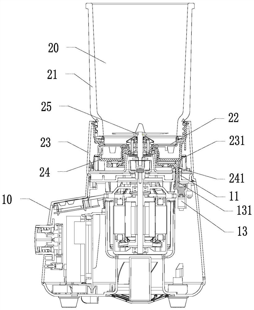
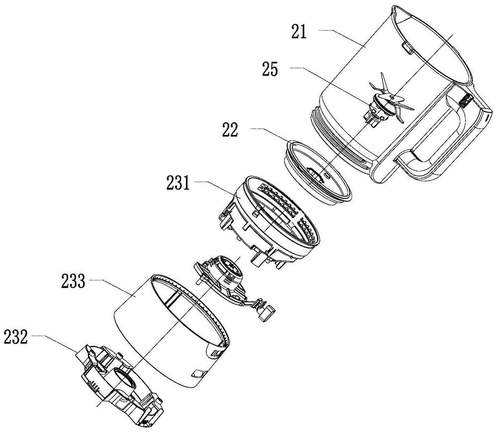
[0044] like Figure 1-Figure 8 As shown, the present invention provides a food processor with a detachable crushing knife assembly, including a main machine 10 and a stirring cup 20 installed on the main machine 10, the stirring cup 20 includes a cup body, and a crushing knife assembly 25 detachably connected to the cup body And the cup holder 23 installed below the cup body, the cup holder 23 is rotatably installed with a rotating bracket 24, the crushing knife assembly 25 penetrates the cup body and locks with the rotating bracket 24, the rotating bracket 24 is provided with an upper positioning structure 241, and the host 10 is provided with The lower positioning structure 11, the rotating bracket 24 rotates the preset stroke to lock the crushing knife assembly 25 and the rotating bracket 24 so that the upper positioning structure 241 is opposite to the lower positioning structure 11 to match the mixing cup 20 with the main machine 10, and the rotation of the rotating bracke...

Embodiment 2

[0057] The difference between the present embodiment and the first embodiment is that the upper positioning structure is a shield provided on the rotating bracket, and the lower positioning structure is a lower coupler on the host.

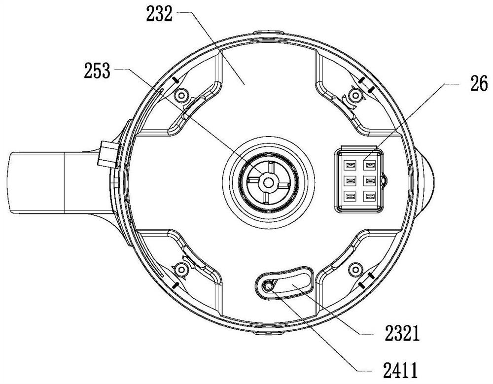
[0058] In this example, if Figure 9-Figure 11As shown, there is an upper coupler inside the cup holder, a lower coupler corresponding to the upper coupler 26 protrudes from the upper surface of the host, and a safety switch is provided inside the host. When the stirring cup is installed on the host, the upper coupler 26 and The lower coupler cooperates to realize electrical connection. The cup holder includes a bottom cover 232. The bottom cover 232 is provided with an avoidance hole 2321 for avoiding the upper coupler 26, and a push rod 2322 for triggering a switch installed in the host. A rotating bracket is provided above the bottom cover 232. 24. The rotating bracket 24 is provided with a gap to avoid the upper coupler 26, and the gap is prov...

Embodiment 3

[0063] The difference between this embodiment and the first embodiment is that the upper positioning structure is a through hole provided on the rotating bracket, and the lower positioning structure is a bump on the main machine.

[0064] In this example, if Figure 12-Figure 15 As shown, the cup holder includes a mounting base 231 and a bottom cover 232, the rotating bracket 24 is rotatably mounted on the bottom of the mounting base 231, the upper positioning structure is a through hole 2412 located in the rotating bracket, and the bottom cover 232 is provided with an avoidance of the lower positioning structure. Hole 2321, the main machine 10 is provided with the lower connector 12, the lower coupler 113 and the lower positioning structure connected with the transmission of the crushing knife assembly. Stroke, the bump 112 is opposite to the through hole 2412. At this time, when the stirring cup is installed, the bump 112 extends into the cup holder and is inserted into the ...


PUM


Abstract

The invention discloses a food processor with a detachable crushing cutter assembly. The food processor comprises a main machine and a stirring cup installed on the main machine, the stirring cup comprises a cup body, the smashing cutter assembly detachably connected with the cup body and a cup base installed below the cup body, and the food processor further comprises a rotating support rotatably installed on the cup base. The smashing cutter assembly penetrates through the cup body and is locked with the rotating support, the rotating support is provided with an upper positioning structure, the main machine is provided with a lower positioning structure, and the rotating support rotates by a preset stroke to lock the smashing cutter assembly and the rotating support so that the upper positioning structure can be opposite to the lower positioning structure, and the stirring cup can be matched with the main machine. When the rotating stroke of the rotating support is smaller than the preset stroke, the upper positioning structure and the lower positioning structure interfere to prevent the stirring cup from being installed on the main machine so that the food processor is prevented from being started when the smashing cutter assembly is not locked, and leakage is prevented.

Description

technical field [0001] The invention belongs to the technical field of food processing, in particular to a food processing machine with a detachable crushing knife assembly. Background technique [0002] In existing food processors, the pulverizer assembly is usually fixed to the bottom of the cup body, which makes it difficult to clean the pulverizer assembly. Even with a cleaning brush, it is difficult to clean the cleaning dead corner under the pulverizer assembly. Therefore, people design the pulverizer to be connected to the cup. Detachable structure of the body, such as fixing the crushing knife assembly on the cutter head, designing the entire cutter head as a detachable structure with the cup body, or detachable the crushing knife assembly through a detachable locking structure or the bottom cover of the cup holder It is fixed on the cutter head, and there are many detachable installation structures, but users usually cannot judge whether it is installed in place whe...

Claims


Application Information

Patent Timeline
Patent Type & Authority Applications(China)
IPC IPC(8): A47J43/046A47J43/07
CPCA47J43/046A47J43/0716A47J43/0722A47J43/0761
Inventor 王旭宁林小财陈明杨开清
Owner JOYOUNG CO LTD
Features
  • R&D
  • Intellectual Property
  • Life Sciences
  • Materials
  • Tech Scout
  • Unparalleled Data Quality
  • Higher Quality Content
  • 60% Fewer Hallucinations
Learn More