Rotor house, magnetic steel module and rotor assembly

A rotor and module technology, applied in the direction of electric components, magnetic circuits, electrical components, etc., can solve the problems of high processing cost of rotor components and weak fixing of magnetic steel modules, so as to avoid the risk of loosening, simple structure, and high efficiency. The effect of installation stability

Pending Publication Date: 2022-06-24
SHANGHAI ELECTRIC WIND POWER GRP CO LTD +1
View PDF1 Cites 0 Cited by
  • Summary
  • Abstract
  • Description
  • Claims
  • Application Information

AI Technical Summary

Problems solved by technology

[0004] The technical problem to be solved by the present invention is to provide a rotor house, a magnetic steel module and a rotor assembly in order to overcome the problem of the weak fixing of the magnetic steel module in the rotor house and the high processing cost of the rotor assembly in the prior art

Method used


Image

  • Rotor house, magnetic steel module and rotor assembly
  • Rotor house, magnetic steel module and rotor assembly
  • Rotor house, magnetic steel module and rotor assembly

Examples


Embodiment 1

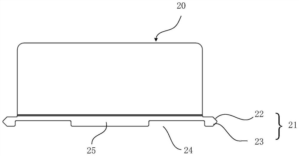
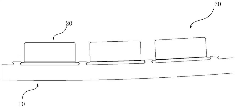
[0057] like Figure 1 to Figure 7As shown, this embodiment provides a rotor assembly 30 , the rotor assembly 30 includes a magnetic steel module 20 and a rotor house 10 , the magnetic steel module 20 is fixed on the rotor house 10 , and the magnetic steel module 20 includes a magnetic steel module 20 and the rotor house 10 . The base plate 25 in contact with the yoke surface, the base plate 25 is made of magnetically conductive material, and the magnetic steel module 20 also includes a cover plate, a magnetic steel and a magnetic steel frame, wherein the cover plate is made of a non-magnetically conductive material, and the magnetic steel frame, The cover plate and the base plate 25 form a closed space for accommodating the magnetic steel. The number of the magnetic steel is at least two. With the above structure, the closed space can protect and prevent the permanent magnets and silicon steel parts.

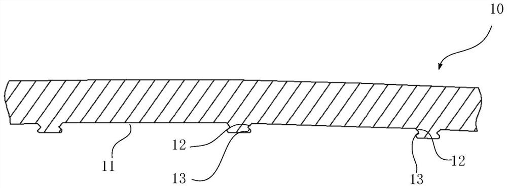
[0058] In this embodiment, the yoke surface of the rotor house 10 is provid...

Embodiment 2

[0065] like Figure 8 to Figure 9 As shown, Embodiment 2 provides a rotor assembly 30, which is different from Embodiment 1 in that the end faces of the ends on both sides of the slot 11 on the yoke surface of the rotor house 10 are semicircular arc surfaces. The semicircular arc surface of one end portion is symmetrically arranged with the semicircular arc surface of the other end portion. The above-mentioned semi-circular arc groove 24 can be customized for a tool with a corresponding symmetrical angle during the manufacturing process. Compared with the T-shaped groove and the dovetail groove, the cutting edge angle of the tool is convenient for cutting, the reaction force that the tool bears is small, and the cutting force is large. , high feed speed and low processing cost.

[0066] It should be noted that the present invention is not limited to the solution in which the ends of the slots or the protrusions are triangular cross-sections and semi-circular arcs, as long as ...

Embodiment 3

[0068] like Figure 10 As shown, Embodiment 3 provides a rotor assembly 30, which is different from Embodiment 1 and Embodiment 2 above in that the protrusion 21 of the base plate 25 of the magnetic steel module 20 does not completely extend from one end of the rotor house 10 along its axis. direction extends to the other end, specifically, as Figure 10 As shown, the protrusions 21 are provided on both sides of the base plate 25, and each side of the base plate 25 is provided with two protrusions 21, and the two protrusions 21 are respectively provided at both ends of the side, and the protrusions 21 The radial protrusions are perpendicular to the rotor housing 10 . It should be noted that the arrangement structure of the protrusions 21 can be adjusted adaptively according to actual needs, which is not specifically limited here.

[0069] To sum up, the present invention adopts the configuration of the protrusions 21 of the base plate 25 of the magnetic steel module 20 and t...


PUM


Abstract

The invention discloses a rotor house, a magnetic steel module and a rotor assembly. Wherein the magnetic yoke surface of the rotor room is provided with a slot, the slot is used for accommodating a magnetic steel module, and the end parts of the two sides of the slot are gradually narrowed along the tangential direction of the rotor room. The magnetic steel module comprises a substrate in contact with a magnet yoke surface of the rotor room, the substrate is provided with a bulge, and the end parts of the two sides of the bulge are gradually narrowed along the tangential direction of the rotor room. According to the scheme, compared with a bolt connection mode in the prior art, the loosening risk caused by bolt installation is avoided, the structure is simple, and assembling is convenient; and on the other hand, compared with the technical scheme of a T-shaped slot in the prior art, the slot on the substrate can enable more magnetic flux to pass through the front surface of the substrate to generate a magnetic gathering effect, so that the magnetic density between the substrate and the rotor room is increased, the suction force between the magnetic steel module and the rotor room is further improved, and the installation stability is improved.

Description

technical field [0001] The invention belongs to the field of permanent magnet direct-drive wind generators, and in particular relates to a rotor house, a magnetic steel module and a rotor assembly. Background technique [0002] The permanent magnet motor and the outer rotor magnet of the wind turbine are mainly fixed by the surface mount. The magnet module is mainly composed of the magnet, the cover and the base plate. This structure is mostly used in permanent magnet wind turbines or high-power permanent magnets. In the magnetic motor, the fixing form with the rotor is mostly T-slot or bolt fixing. For example, a Chinese patent with publication number CN103534911B discloses a generator rotor and a magnetic steel structure, and the T-shaped structure is installed by drilling holes on the surface of the rotor. nut to form the installation guide groove, and finally insert the magnet into the groove to fix it. [0003] The processing cost of the bolt fixing method is high, esp...

Claims


Application Information

Patent Timeline
Patent Type & Authority Applications(China)
IPC IPC(8): H02K1/2791
CPCH02K1/2786
Inventor 吴立建李进施杨卢江跃孙永岗赵方伟
Owner SHANGHAI ELECTRIC WIND POWER GRP CO LTD
Why Eureka
Try Eureka