
An automatic punching equipment for metal pipes

A technology for punching equipment and metal pipes, which is applied in metal processing equipment, drilling/drilling equipment, metal processing, etc., and can solve the problems of low drilling efficiency of round pipes, so as to improve drilling efficiency, save power, and ensure The effect of accurate punching

Active Publication Date: 2022-07-05
江苏源清管业有限公司
View PDF6 Cites 0 Cited by
  • Summary
  • Abstract
  • Description
  • Claims
  • Application Information

AI Technical Summary

Problems solved by technology

[0004] In view of the above-mentioned related technologies, the inventor believes that there are the following defects: because the round tube needs to be drilled with eight through holes, the worker needs to clamp, rotate and punch the same round tube multiple times, resulting in the hole punching of the round tube. Inefficient, so needs to be improved

Method used


Image

  • An automatic punching equipment for metal pipes
  • An automatic punching equipment for metal pipes
  • An automatic punching equipment for metal pipes

Examples


Embodiment Construction

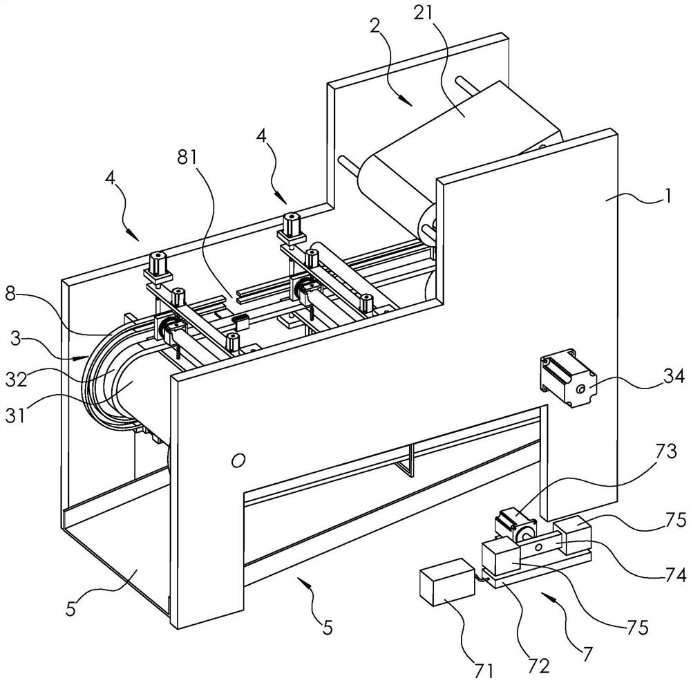
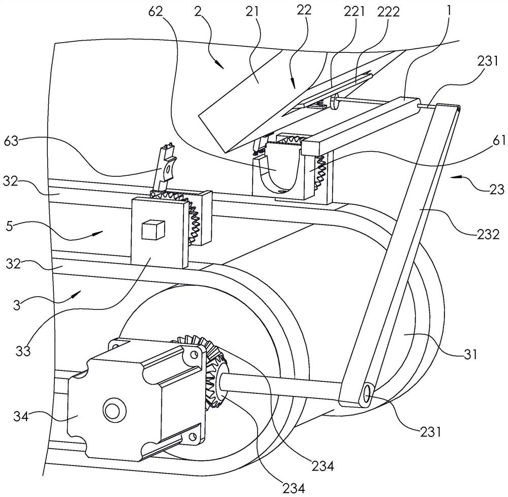
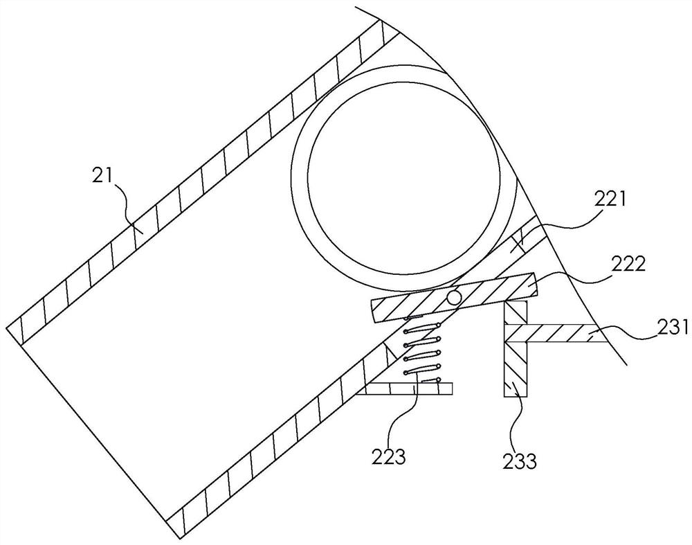
[0056] Attached to the following Figure 1-10 This application will be described in further detail.

[0057] The embodiment of the present application discloses an automatic punching device for metal pipes. like figure 1 As shown in the figure, an automatic punching device for metal pipes includes a bracket 1, and the bracket 1 is provided with a feeding mechanism 2, a conveyor belt 3, two sets of punching mechanisms 4 and an unloading mechanism 5, and the conveyor belt 3 is provided with several The jig 6 arranged in a ring, the feeding mechanism 2 is used to feed the round pipe to the jig 6 of the conveyor belt 3, the jig 6 clamps and fixes the round pipe, and the conveyor belt 3 transports the jig 6 and the round pipe to the punching mechanism 4 At the position, the punching mechanism 4 punches the end of the round pipe, and the blanking mechanism 5 blanks the finished round pipe.

[0058] like figure 1 As shown, the feeding mechanism 2 includes a channel 21 fixed on th...


PUM


Abstract

The application relates to the technical field of metal processing, and in particular to an automatic punching device for metal pipes, which includes a support, on which is provided a conveyor belt, an annular track and two sets of punching mechanisms, and the conveyor belt is provided with a plurality of annular Arranged mounting racks, the mounting rack is rotatably connected with a clamp, the clamp is provided with a rotating gear, and the clamp is slidably matched with the annular track; the annular track is provided with two gaps, and both gaps are provided with rotating gears. Gear rack; one group of punching mechanism is located between the two racks, and the punching mechanism includes a driving component and two groups of punching units arranged at an upper and lower interval, and the punching unit includes two groups of drilling rigs arranged at both ends of the round pipe and the connecting plates connected to the two sets of drilling rigs, and the driving component drives the two connecting plates to approach or move away from each other in the vertical direction. The present application can improve the punching efficiency of the round pipe.

Description

technical field [0001] The present application relates to the technical field of metal processing, and in particular, to an automatic punching device for metal pipes. Background technique [0002] Punching is the cutting or drilling of a hole in a solid or solid material with an implement with a drill. [0003] In industrial production, in order to facilitate the installation of joints at the end of the metal round pipe, it is usually necessary to drill four circumferentially arranged through holes at both ends of the round pipe to facilitate the penetration of bolts. In the process of round pipe processing, the round pipe needs to be clamped and fixed first, and then the end of the round pipe is punched by a drilling machine. [0004] In view of the above-mentioned related art, the inventor believes that there are the following defects: because the round pipe needs to punch a total of eight through holes, the worker needs to perform multiple clamping, rotation and punching...

Claims


Application Information

Patent Timeline
Patent Type & Authority Patents(China)
IPC IPC(8): B23B39/16B23B41/00B23Q3/00B23B47/18B23Q5/34B23Q7/00
CPCB23B39/16B23Q7/003B23Q7/00B23Q3/00B23Q5/34B23B41/00
Inventor 不公告发明人
Owner 江苏源清管业有限公司
Learn More