Efficient scissor foot assembling equipment

A technology for assembling equipment and scissors legs, applied in the field of scissors legs, can solve the problems of inconvenient, time-consuming, labor-intensive, and unsatisfactory holding and clamping by human hands, saving manpower and material resources, improving assembly effects, and improving production efficiency. Effect

Pending Publication Date: 2021-08-13
苏州亿源精密模具有限公司
View PDF5 Cites 0 Cited by
  • Summary
  • Abstract
  • Description
  • Claims
  • Application Information

AI Technical Summary

Problems solved by technology

[0004] However, due to the small size of the inner frame and the outer frame of the scissors, it is inconvenient to hold and clamp the scissors by hand. Therefore, in the related art, manual assembly of the scissors is time-consuming, laborious, and inefficient. Five workers a day Only 20,000 to 30,000 pieces can be assembled, which cannot meet the needs of actual production

Method used


Image

  • Efficient scissor foot assembling equipment
  • Efficient scissor foot assembling equipment
  • Efficient scissor foot assembling equipment

Examples


Embodiment 1

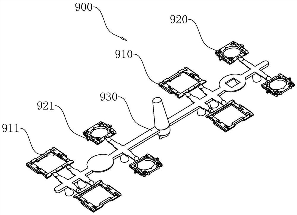
[0045] The present application discloses a high-efficiency assembly equipment of scissor legs, which is used for cutting the outer frame 910 and the inner frame 920 of the batching unit 900 from the connecting rod 930 and assembling them together. refer to figure 1 , in this embodiment, the batching unit 900 includes a connecting rod 930 , four outer frames 910 and four inner frames 920 . The four outer frames 910 are symmetrically connected in pairs on opposite sides of the connecting rod 930 ; similarly, the four inner frames 920 are connected in pairs on opposite sides of the connecting rod 930 in a symmetrical manner. On the same side of the connecting rod 930, the outer frame 910 and the inner frame 920 are arranged alternately. At the same time, the inner frame 920 is provided with a pair of rotating shafts 921, and the two rotating shafts 921 are arranged symmetrically on opposite sides of the outer ring of the inner frame 920; Both sides; the shaft groove 911 is used...

Embodiment 2

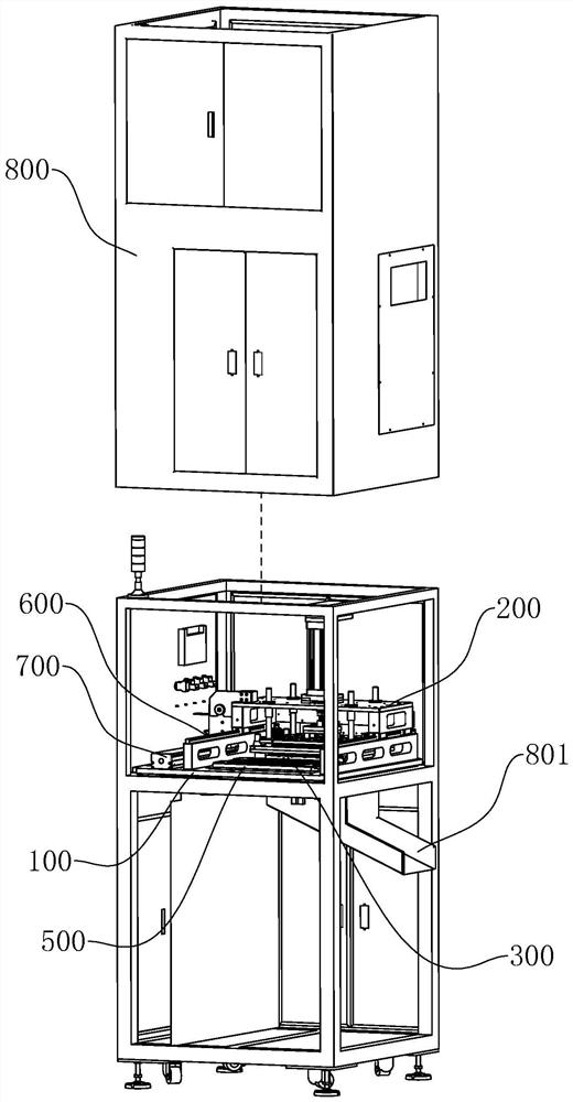
[0074] The embodiment of the present application discloses an efficient assembly equipment for scissor legs. This embodiment is basically the same as Embodiment 1, the difference is that, with reference to Figure 9 , a baffle 770 is provided on one side of the slide table 730; meanwhile, the workbench 100 is fixedly connected with a laser range finder 780 that cooperates with the baffle 770. The laser rangefinder 780 emits light to the baffle 770 and measures the distance between the two, through which the moving distance of the press-cut assembly 200 in the direction along the slide rail 600 can be accurately judged, so that the press-cut assembly 200 can be precisely positioned, Make the assembly of the inner frame 920 and the outer frame 910 more smooth. Moreover, compared with Embodiment 1, the positioning of the laser rangefinder 780 does not need to be limited by the number and position of the U-shaped groove photoelectric switches 760, so the positioning is more flexi...


PUM


Abstract

The invention relates to efficient scissor foot assembling equipment. The equipment comprises a workbench, a pressing and cutting assembly and a bottom template; the bottom template is used for placing a batching unit; the batching unit comprises an outer frame and an inner frame which are connected to a connecting rod; the bottom template is fixedly connected to the workbench and comprises a plurality of working units; each working unit comprises an inclined bottom groove and a flat bottom groove which are in one-to-one correspondence; a stop block is arranged on the bottom lower side of each inclined bottom groove; the pressing and cutting assembly comprises an upper pressing plate, a middle pressing plate, a lower pressing plate, a supporting structure, a stamping head, an outer frame pressing block and a material taking rod; the stamping head is used for stamping to separate the outer frame and the inner frame from the connecting rod; the outer frame pressing block is used for pressing the outer frame to be obliquely arranged; the material taking rod is inserted into an inner ring of the inner frame and carries the inner frame to be clamped into an inner ring of the outer frame. Full-automatic assembling of the inner frame and the outer frame of a scissor foot can be achieved, and manpower and material resources are saved; not only is the production efficiency improved, but also the assembling quality is improved.

Description

technical field [0001] The present application relates to the field of scissors, in particular to a high-efficiency assembly equipment for scissors. Background technique [0002] The scissors foot is an important component of the computer keyboard, which consists of an inner frame and an outer frame. Wherein, the outer ring of the inner frame matches the inner ring of the outer frame; and the opposite sides of the outer ring of the inner frame are respectively provided with rotating shafts, and the opposite sides of the inner ring of the outer frame are respectively provided with rotating shafts corresponding to and matched with each other. shaft groove. The inner frame is locked in the outer frame to form a whole by the rotating shaft being snapped into the corresponding shaft groove. [0003] At present, in the related art, the assembly of the outer frame and the inner frame is often realized by manual clamping. First, snap the rotating shaft on one side of the inner fr...

Claims


Application Information

Patent Timeline
Patent Type & Authority Applications(China)
IPC IPC(8): B23P19/02
CPCB23P19/02
Inventor 叶元革叶泽仁叶毅
Owner 苏州亿源精密模具有限公司
Why Eureka
Try Eureka