Charging device for electrical automation equipment
A technology of electrical automation and charging devices, applied in the field of automation, can solve the problems of charging devices stuck, intertwined, reduced convenience and safety, etc., and achieve the effect of preventing damage to the outer skin and preventing electric leakage
- Summary
- Abstract
- Description
- Claims
- Application Information
AI Technical Summary
Problems solved by technology
Method used
Image

Examples
Embodiment 1
[0028] Figure 1 to Figure 6 Shown:
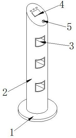
[0029] The invention provides a charging device for electrical automation equipment,
[0030] Its structure includes a positioning base 1, a charging pile 2, an actuator 3, a display terminal 4, and a switch key 5. The positioning base 1 is engaged with the charging pile 2, and the actuator 3 is embedded in the charging pile 2. The display terminal 4 is electrically connected to the movable device 3, and the switch key 5 is in clearance fit with the display terminal 4.
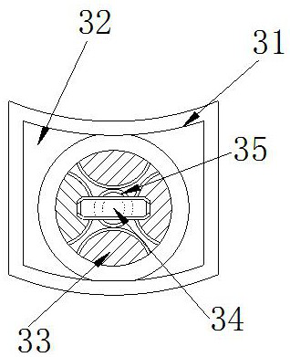
[0031] The mover 3 is provided with a casing 31, a groove 32, a baffle 33, a charging block 34, and a roll collector 35, the casing 31 and the groove 32 are integrated, and the baffle 33 is embedded in the edge of the groove 32 , the charging block 34 and the baffle plate 33 carry out a clearance fit, and the coil collector 35 is installed on the rear end of the charging block 34 and is electrically connected, and the baffle plate 33 is provided with four pieces in total...
Embodiment 2
[0039] Figure 7 to Figure 9 Shown:
[0040] The invention provides a charging device for electrical automation equipment,
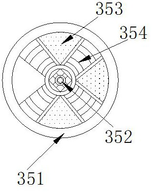
[0041] Its structure includes that the wire trough 352 is provided with a positioning block c1, a layer body c2, and an extruder c3, the positioning block c1 is embedded in the center of the layer body c2, and the extruder c3 is installed in the layer body c2 , the extruder c3 is provided with a total of four and forms a ring shape. The extruder c3 can effectively prevent the wires from being pulled at different positions for protection through its own number, and prevent damage caused by continuous scraping with the inner wall .
[0042] Wherein, the extruder c3 is provided with a contact layer c31, a holder c32, and a fixed shaft c33, the contact layer c31 and the holder c32 are in clearance fit, and the fixed shaft c33 is installed on the outer layer of the holder c32, so The fixed shaft c33 is in a solid state and corresponding bolts are installed...
PUM
 Abstract
Description
Claims
Application Information
 - Generate Ideas
- Intellectual Property
- Life Sciences
- Materials
- Tech Scout
- Unparalleled Data Quality
- Higher Quality Content
- 60% Fewer Hallucinations
Browse by: Latest US Patents, China's latest patents, Technical Efficacy Thesaurus, Application Domain, Technology Topic, Popular Technical Reports.
© 2025 PatSnap. All rights reserved.Legal|Privacy policy|Modern Slavery Act Transparency Statement|Sitemap|About US| Contact US: help@patsnap.com