Intelligent guiding rule for plane range measurement

An extremely poor and intelligent technology, applied in the field of measurement, can solve the problems of not being able to obtain the extreme difference, and achieve the effect of convenient and accurate measurement

Active Publication Date: 2021-08-13
中建五局第四建设有限公司 +2
View PDF5 Cites 2 Cited by
  • Summary
  • Abstract
  • Description
  • Claims
  • Application Information

AI Technical Summary

Problems solved by technology

[0004] The purpose of the present invention is to solve the problem that the range cannot be obtained in the prior art, and propose an intelligent ruler for plane range measurement

Method used


Image

  • Intelligent guiding rule for plane range measurement
  • Intelligent guiding rule for plane range measurement
  • Intelligent guiding rule for plane range measurement

Examples


Embodiment 1

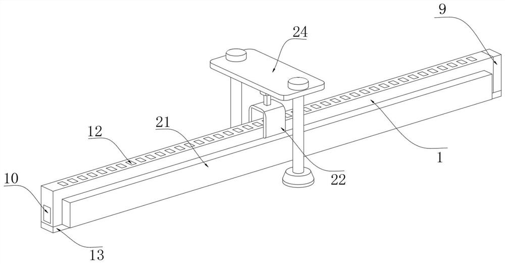
[0026] refer to Figure 1-5 , an intelligent ruler for plane range measurement, comprising a ruler body 1, a trigger chamber 2 is opened on the upper part of the ruler body 1, and a plurality of distribution plates 4 are connected to the inner wall of the trigger chamber 2 through a plurality of return springs 3, each The bottoms of each distribution plate 4 are fixed with connecting rods 5, and the bottom of each connecting rod 5 runs through the side wall of the trigger cavity 2 and is fixed with a cutout plate 6, and the bottom of each cutout plate 6 is fixed with a contact rod 7, each The upper ends of each light-cutting plate 6 are equipped with a positioning mechanism, the outer wall of the ruler body 1 is provided with a graphic display mechanism, the outer wall of the ruler body 1 is connected with a co-measurement mechanism, and the bottom of the ruler body 1 is fixed with a protective bottom plate 13, which is used for Avoid damage to the contact rod 7 and ensure mea...

Embodiment 2

[0037] refer to figure 1 and Figure 4 The difference between the present embodiment and the first embodiment lies in the difference of the graphic display mechanism. In the present embodiment, the graphic display mechanism includes side loading grooves 19 opened on both sides of the ruler body 1, and the inner walls of the two side loading grooves 19 are respectively fixed with The side display panel 20 and the side light box 21, the side wall of the side display panel 20 is coated with a photochromic substance, and the side wall of the side display panel 20 is provided with a scale;

[0038] When measuring, the light emitted by the side light box 21 will be able to completely cover each light-cutting plate 6, and there will be no common blocking position between each light-cutting plate 6 due to overlap, and the light that can be blocked by each light-cutting plate 6 is relatively independent , so the colored lines displayed on the side display panel 20 will be independent ...


PUM


Abstract

The invention discloses an intelligent guiding rule for plane range measurement. The intelligent guiding rule comprises a rule body, a trigger cavity is formed in the upper part of the ruler body; the inner wall of the trigger cavity is connected with a plurality of distribution plates through a plurality of reset springs, and a connecting rod is fixed to the bottom of each distribution plate; the bottom of each connecting rod penetrates through the side wall of the trigger cavity and is fixedly provided with a light intercepting plate, the bottom of each light intercepting plate is fixedly provided with a feeler lever, and the upper end of each light intercepting plate is provided with a positioning mechanism. By arranging the end lamp box, the end lamp box emits ultraviolet light to the inside of the ruler body, and the ultraviolet light parallel to the ruler body can penetrate through the light intercepting plates to fall on the end display plate; because the heights of the light intercepting plates at different positions are different, the light falling on the end display plate is the remaining part after being intercepted by the light intercepting plates; therefore, the height range of the light intercepting plate can be easily measured and calculated through light rays falling on the uppermost part and the lowermost part of the end display plate, so that the range of the wall surface of the measured position is obtained.

Description

technical field [0001] The invention relates to the technical field of measurement, in particular to an intelligent ruler for plane extreme difference measurement. Background technique [0002] A ruler is a detection tool. The rulers are classified into student rulers, vertical detection rulers, diameter measuring rulers and engineering quality detectors. Check whether the walls and tiles are flat and vertical. Check whether the floor keel is level and flat. [0003] The existing ruler can measure various attributes of the plane to obtain various values, but it cannot measure the range value of the wall, etc., especially when measuring the top, it is often necessary to use a laser leveling instrument, and it is necessary to set up multiple point position, which makes the overall measurement very inconvenient, and the measurement of the wall surface by the existing ruler is only reflected in the vertical direction, which cannot effectively show the flatness of the wall sur...

Claims


Application Information

Patent Timeline
Patent Type & Authority Applications(China)
IPC IPC(8): G01C15/00
CPCG01C15/00
Inventor 游杰勇王英豪万东波王春光蔡见阳贾国华宋叶群陈星曹光阁杨迎宾李海通王帅严森原辰王鹏超
Owner 中建五局第四建设有限公司
Why Eureka
Try Eureka