
Rotary ball stacked ring type shear box and ring shear apparatus with same

A ball-stacked ring-type and shear box technology, which is applied in the field of ring shear instruments, can solve problems affecting test accuracy and achieve the effects of improving test accuracy, overcoming lateral friction, and strong practicability

Pending Publication Date: 2021-08-13
西安建创地岩信息科技有限公司
View PDF0 Cites 1 Cited by
  • Summary
  • Abstract
  • Description
  • Claims
  • Application Information

AI Technical Summary

Problems solved by technology

[0006] The object of the present invention is to provide a kind of rotating ball stacked ring shear box and the ring shear instrument with the shear box, because in the prior art, there is a certain friction force between the side wall of the sample and the inner wall of the sample box, which affects the The problem of test accuracy

Method used


Image

  • Rotary ball stacked ring type shear box and ring shear apparatus with same
  • Rotary ball stacked ring type shear box and ring shear apparatus with same
  • Rotary ball stacked ring type shear box and ring shear apparatus with same

Examples


Embodiment 1

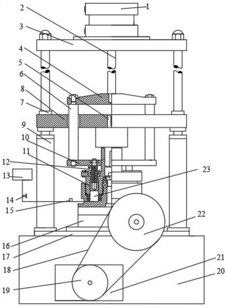
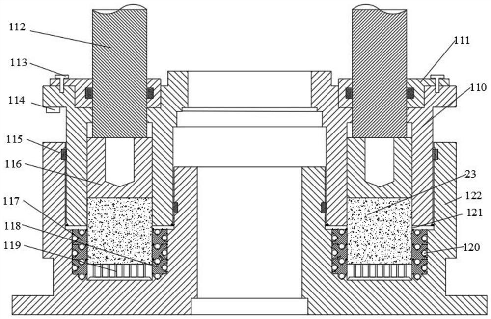
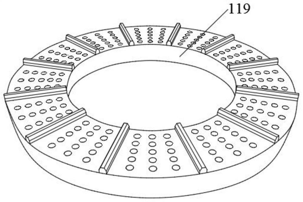
[0036] like Figure 2-Figure 7 As shown, the embodiment of the present invention provides a rotary ball stacked ring shear box and a ring shear instrument with the shear box, including: figure 2 , 5 As shown in , 6, the upper box includes: a cylinder I110, the middle part of which is provided with an installation hole I, the bottom of which is provided with a ring part I around the installation hole I, and an annular groove I is provided around the center of the ring part I, and the ring groove I The inner bottom of the I is evenly distributed with a plurality of guide holes for piercing the pressure column 112; the pressure ring 116 is arranged in the annular groove 1, and its top is connected to the lower end of the pressure column 112; figure 2 , 4 7. The lower box shown in 7, which includes: a cylinder II122, the middle of which is provided with an installation hole II, the top of which is provided with a ring II around the installation hole II, and an annular groove I...

Embodiment 2

[0038] On the basis of Embodiment 1, in order to overcome the problem that the ring body and the ball 120 of the stacked ring fall during the disassembly and assembly of the annular sample 23, the device also includes two annular backing plates 121, two backing plates 121 Correspondingly arranged on the top of the inner moving ring 118 and the outer moving ring 117, and the backing plate 121 and the inner wall of the annular groove II are fixed.

[0039] Wherein, the width of the backing plate 121 is greater than that of the ring body.

Embodiment 3

[0041] On the basis of Example 1, in order to further reduce the friction between the ring sample 23 and the inner wall of the ring groove II of the lower box, the space between the ball 120 and the ring body is filled with butter.


PUM


Abstract

The invention relates to a rotary ball stacked ring type shear box and a ring shear apparatus with the same, and the rotary ball stacked ring type shear box comprises: an upper box, and a lower box, wherein an inner movable ring, an outer movable ring which are arranged in the lower box, the inner movable ring and the outer movable ring are each of a stacked ring structure, and each stacked ring structure comprises a plurality of ring bodies which are sequentially stacked together in the direction of the center line of the outer movable ring; and balls which are uniformly distributed on the contact surfaces of every two adjacent ring bodies. According to the device, the ball stacked ring type shear box is arranged, the outer movable ring and the inner movable ring are arranged in the lower box of the shear box and are both of stacked ring structures, the rotary table rotates to drive the lower box to rotate, and the stacked ring structures in the lower box rotate along with the lower box, so that the lateral friction force between the side wall of the lower box of the shear box and an annular sample is overcome in the test process, and the shear box is high in practicability and worthy of popularization.

Description

technical field [0001] The invention relates to the field of rock and soil engineering mechanical performance test equipment, in particular to a rotating ball stacked ring shear box and a ring shear instrument with the shear box. Background technique [0002] The ring shear instrument is a kind of geotechnical test equipment that can measure the mechanical properties of the soil under the condition of large shear displacement. It is mainly used to study the residual strength properties of the soil after the shear plane is formed. The study of the mechanical mechanism of geological disasters and the study of the progressive failure process of the slope has important academic significance and engineering application value. [0003] In the conventional ring shear test, the area of ​​the shear surface of the sample is kept constant during the test, and large deformation shear occurs under continuous displacement. During the test, vertical pressure and torsional shear are applied...

Claims


Application Information

Patent Timeline
Patent Type & Authority Applications(China)
IPC IPC(8): G01N3/24G01N3/02
CPCG01N3/02G01N3/24
Inventor 李荣建谢全荣李荣锦刘伯玲
Owner 西安建创地岩信息科技有限公司
Learn More