
Clutch-free through shaft type inner rotor hub motor

A clutchless, in-wheel motor technology, applied in the direction of electromechanical devices, electrical components, electric components, etc., can solve the problem that the volume of the motor body cannot be further enlarged, the internal structure of the in-wheel motor cannot be further optimized, and the outer contour of the hub shell cannot be further enlarged and other problems, to achieve the effect of simple structure, increased volume, and improved power

Pending Publication Date: 2021-08-13
SUZHOU SHENGYI MOTOR
View PDF2 Cites 0 Cited by
  • Summary
  • Abstract
  • Description
  • Claims
  • Application Information

AI Technical Summary

Problems solved by technology

[0005] The clutch inside the existing thru-shaft hub motor and its assembly structure with the planetary reduction mechanism occupy a large amount of space inside the hub shell, so that the volume of the motor body cannot be further enlarged, and the power of the motor cannot be further increased.
In addition, due to the existence of the clutch, the internal structure of the hub motor cannot be further optimized
Taking the through-shaft hub motor (application number 202020883276.X) and the through-axis inner rotor hub motor (application number 201922247168.3) of the single-stage deceleration transmission originally applied for by the applicant as examples, it can be seen that due to the limitation of the clutch size assembly, the hub The outer contour of the shell cannot be further enlarged, so the volume of the motor body cannot be increased
In addition, the clutch can only be protruded at the front of the planetary reduction mechanism during assembly, which instead causes the axial size of the entire hub motor to increase and the structure is not compact
Moreover, in this type of hub motor, the assembly structure between the clutch and the planetary reduction mechanism is complicated and cumbersome, which causes many structural restrictions on the axial positioning of the motor body
[0006] In addition, a type of through-shaft hub motor in the industry is currently manufactured with the function of a generator, and the existence of the clutch restricts the two-way rotation of the rotor shaft, which is not conducive to the application as a generator.

Method used


Image

  • Clutch-free through shaft type inner rotor hub motor

Examples


Embodiment

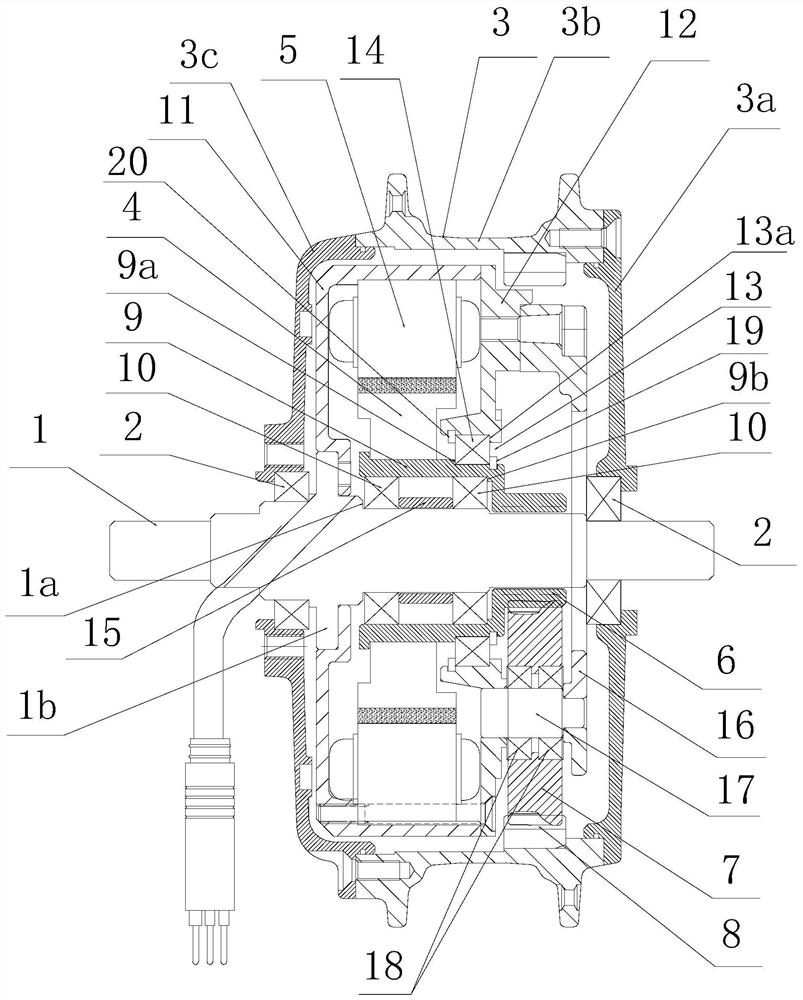
[0024] Embodiment: combine below figure 1 The specific implementation of the clutchless through-shaft inner rotor hub motor provided by the present invention is described as follows:

[0025] first as figure 1 As shown, the clutchless through-shaft inner rotor hub motor provided in this embodiment has a hub shell 3 assembled on the through-shaft 1 through the shell bearings 2 at both ends, and a motor body and a planetary body arranged in the hub shell 3. deceleration mechanism. The hub shell 3 described in this embodiment is formed by fastening the hub front cover plate 3a, the hub middle ring shell 3b and the hub rear cover plate 3c sequentially and then fixing them with screws (marking omitted). The hub front cover plate 3a and the hub The rear cover 3c is assembled on the through shaft 1 through the housing bearing 2 .

[0026] still as figure 1 As shown, the motor body in this embodiment is composed of a rotor 4, a stator 5, a center sleeve 9, a bearing group composed...


PUM


Abstract

The invention discloses a clutch-free through shaft type inner rotor hub motor comprising a hub shell assembled on a through shaft through a shell bearing, and a motor body and a planetary reduction mechanism which are arranged in the hub shell; the motor body comprises a rotor and a peripheral stator, and the planetary reduction mechanism comprises a sun gear and a plurality of planetary gears meshed with the sun gear; and the planetary gears are meshed with an inner gear ring fixed on the inner side of the hub shell. The motor is characterized in that the rotor is fixed on a central sleeve, the central sleeve is assembled on a through shaft through a bearing pack, and the bearing pack comprises two or more rotor inner support bearings which are axially distributed along the through shaft; the motor body further comprises an inner concave shell fixed on the through shaft and an inner cover plate buckled and fixed with the inner concave shell; the stator is fixed on the inner circumference of the inner concave shell, and the front end of the central sleeve penetrates through an opening hole formed in the inner cover plate and is integrally molded with the sun gear; and a rotor outer support bearing is also arranged between the central sleeve and the opening hole. The internal structure of the motor is more optimized, and the motor body part can be enlarged favourably and the power can be improved.

Description

technical field [0001] The invention relates to a clutchless through-shaft inner rotor hub motor. Background technique [0002] Hub motors are the core power components of small electric vehicles, such as electric bicycles. At present, the structure forms of hub motors in the industry are mainly divided into two-stage type and through-shaft type. The two-stage type, as the name implies, is to make the main shaft of the hub motor into two half-shafts on the left and right. Its characteristic is that the sun of the planetary reduction mechanism can be The gear is placed between the two half shafts, ensuring that the diameter of the sun gear is not limited by the diameter of the main shaft. In this way, the number of teeth of the sun gear can be further reduced, thereby further increasing the reduction ratio of the hub motor. [0003] However, the disadvantages of the two-stage hub motor are also significant. The support strength of the two-stage half-shaft is low, which limi...

Claims


Application Information

Patent Timeline
Patent Type & Authority Applications(China)
IPC IPC(8): H02K5/04H02K5/16H02K1/28H02K1/18H02K7/116B60K7/00
CPCH02K5/04H02K5/165H02K1/28H02K1/185H02K7/116B60K7/0007
Inventor 温群峰
Owner SUZHOU SHENGYI MOTOR
Learn More