
Underwater sealing structure of electric push-pull rod

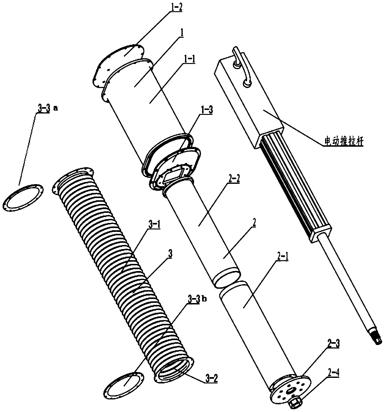
A sealing structure and electric push technology, which is applied in the direction of electric components, electrical components, electromechanical devices, etc., can solve the problems of electric push-pull rod screw corrosion, precision drop, jamming, etc., and achieve low requirements for machining accuracy and mechanical assembly accuracy , The internal space is abundant, and the effect of maintaining the sealing effect

Active Publication Date: 2020-05-12
航天时代(青岛)海洋装备科技发展有限公司
View PDF4 Cites 0 Cited by
  • Summary
  • Abstract
  • Description
  • Claims
  • Application Information

AI Technical Summary

Problems solved by technology

[0003] However, the existing electric push-pull rods, due to their structural limitations, may cause faults such as circuit short circuit, lead screw corrosion, decreased accuracy or jamming when used underwater; , cable interface and other parts are well sealed, and a special waterproof sealing ring combination is used between the output rod and the cylinder body, but because there is always relative sliding between the output rod and the cylinder body during use, the waterproof sealing ring is also It is impossible to scrape off the water on the surface of the output rod. When working underwater for a long time, the water will slowly accumulate with the movement of the output rod and penetrate into the cylinder of the electric push-pull rod, resulting in corrosion of the lead screw of the electric push-pull rod , leading to equipment failure or life reduction

Method used


Image

  • Underwater sealing structure of electric push-pull rod
  • Underwater sealing structure of electric push-pull rod
  • Underwater sealing structure of electric push-pull rod

Examples


Embodiment Construction

[0029] The technical solutions in the embodiments of the present invention will be further described below in conjunction with the accompanying drawings, wherein the strength described is only a part of the embodiments of the present invention, rather than all embodiments. Based on the embodiments of the present invention, all other embodiments obtained by persons of ordinary skill in the art without making creative efforts, all belong to the protection scope of the present invention.

[0030] The present invention provides a specific embodiment of the underwater sealing structure of the electric push-pull rod. Specifically, the electric push-pull rod described in the embodiment of the present invention is a linear series type, that is, the servo motor and the cylinder body are located on the same axis; It can be a parallel structure, that is, the axis of the servo motor is parallel to the axis of the cylinder and does not coincide.

[0031] see figure 1 As shown in FIG. 2( a...


PUM


Abstract

The invention relates to an underwater sealing structure of an electric push-pull rod, and belongs to the field of sealing structures. The underwater sealing structure comprises an equipment cavity assembly, a hard sheath assembly and a flexible sheath assembly. The underwater sealing structure is mainly used for solving the sealing problem when the electric push-pull rod works underwater for a long time, and the principle is that the electric push-pull rod is isolated from the water environment through the flexible sheath assembly, and the hard sheath assembly provides framework support for the flexible sheath assembly; when the electric push-pull rod stretches and retracts back and forth, the hard sheath assembly and the flexible sheath assembly can move along with the power rod, and theinfluence on the movement function of the electric push-pull rod is reduced while water tightness is ensured. The underwater sealing structure has the advantages that on the premise that the sealingstructure of the electric push-pull rod is not changed, the underwater sealing structure is additionally arranged, the electric push-pull rod which does not have the underwater working capacity can normally work underwater, and the environment range which the electric push-pull rod can adapt to can be expanded.

Description

technical field [0001] The invention relates to an underwater sealing structure of an electric push-pull rod, which belongs to the field of underwater sealing structures. Background technique [0002] As a linear drive power device, the electric push-pull rod is widely used in motion mechanisms such as robots and mechanical arms. [0003] However, the existing electric push-pull rods, due to their structural limitations, may cause faults such as circuit short circuit, lead screw corrosion, decreased accuracy or jamming when used underwater; , cable interface and other parts are well sealed, and a special waterproof sealing ring combination is used between the output rod and the cylinder body, but because there is always relative sliding between the output rod and the cylinder body during use, the waterproof sealing ring is also It is impossible to scrape off the water on the surface of the output rod. When working underwater for a long time, the water will slowly accumulate...

Claims


Application Information

Patent Timeline
Patent Type & Authority Applications(China)
IPC IPC(8): H02K5/10H02K5/12H02K7/06
CPCH02K5/10H02K5/12H02K7/06H02K2213/03
Inventor 胡常青胡宇彭克侠王虹阳范慧佳
Owner 航天时代(青岛)海洋装备科技发展有限公司
Learn More