
Photovoltaic thermoelectric power generation device suitable for mountain environment

A technology of thermoelectric power generation and thermoelectric power generation sheet, applied in the field of solar power generation, can solve the problems of waste of solar thermal energy, decrease of conversion efficiency, temperature rise of photovoltaic cells, etc., to increase power output, improve overall efficiency, and solve the effect of cooling and heat dissipation

Pending Publication Date: 2021-08-13
国家电投集团贵州金元威宁能源股份有限公司
View PDF0 Cites 0 Cited by
  • Summary
  • Abstract
  • Description
  • Claims
  • Application Information

AI Technical Summary

Problems solved by technology

In fact, the photoelectric conversion efficiency of current solar cells is only below 20%, and more than 80% of light energy cannot be converted into useful energy.
Therefore, on the one hand, it will cause a great waste of solar heat energy, and at the same time, the heat energy that is not converted into electrical energy will also cause the temperature of the photovoltaic cell to rise, and the conversion efficiency of the photovoltaic cell will decrease with the increase of the conversion temperature. The heating of the photovoltaic cells by heat will cause the conversion efficiency to decrease, and it is necessary to cool them. On the one hand, the photoelectric conversion efficiency of solar energy can be improved, and on the other hand, excess heat can be recovered and utilized by a certain cooling method to improve the comprehensive utilization of solar energy. efficiency
Due to the uneven terrain of mountainous photovoltaic power stations and insufficient water sources, it is unrealistic to use water to cool photovoltaic panels

Method used


Image

  • Photovoltaic thermoelectric power generation device suitable for mountain environment
  • Photovoltaic thermoelectric power generation device suitable for mountain environment
  • Photovoltaic thermoelectric power generation device suitable for mountain environment

Examples


Embodiment Construction

[0023] In order to make the object, technical solution and advantages of the present invention more clear, the present invention will be further described in detail below in conjunction with the accompanying drawings and embodiments. It should be understood that the specific embodiments described here are only used to explain the present invention, not to limit the present invention.

[0024] Before describing the various embodiments of the present application in detail, first briefly describe the inventive concept of the present application: For mountain photovoltaics, due to insufficient water sources, it is unrealistic to use water for heat dissipation, and it will cause waste of solar energy. The heat is used for thermoelectric power generation. According to the law of energy conservation, the heat of the photovoltaic panel is converted into electrical energy through thermoelectric power generation, so that the photovoltaic panel can be cooled. In the case of no increase in...


PUM


Abstract

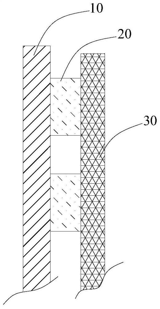
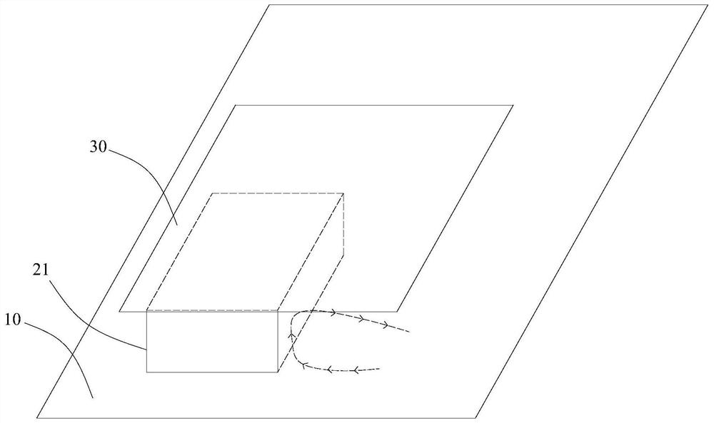
The invention discloses a photovoltaic thermoelectric power generation device suitable for a mountain environment. The photovoltaic temperature difference power generation device comprises a photovoltaic cell panel, a thermoelectric power generation unit and a heat dissipation plate. The thermoelectric power generation unit comprises a plurality of thermoelectric power generation sheets which are distributed at intervals, and each thermoelectric power generation sheet is clamped between the back face of the photovoltaic cell panel and the heat dissipation plate. The two ends of each thermoelectric power generation sheet generate temperature difference under the combined action of the photovoltaic cell panel and the heat dissipation plate. In a mountainous area lacking water resources, the photovoltaic thermoelectric power generation device effectively solves the problem of cooling and heat dissipation of the photovoltaic cell panel, meanwhile, waste heat of the photovoltaic panel is used for power generation by the thermoelectric power generation sheets, electric energy output is additionally increased, and the total efficiency of photovoltaic-thermoelectric power generation is improved.

Description

technical field [0001] The invention belongs to the technical field of solar power generation, and in particular relates to a photovoltaic thermoelectric power generation device suitable for mountain environments. Background technique [0002] With the increasingly prominent energy and environmental issues, solar photovoltaic power generation technology has received more and more attention as a way of utilizing solar energy. In solar photovoltaic power generation technology, solar photovoltaic power generation can only convert light energy equal to the bandwidth into electrical energy, and light energy greater than the forbidden band width can only be lost in the form of heat. In fact, the photoelectric conversion efficiency of current solar cells is only below 20%, and more than 80% of light energy cannot be converted into useful energy. Therefore, on the one hand, it will cause a great waste of solar heat energy, and at the same time, the heat energy that is not converted...

Claims


Application Information

Patent Timeline
IPC IPC(8): H02S10/10H02N11/00H02S40/42
CPCH02N11/002H02S10/10H02S40/42Y02E10/50
Inventor 郑发松叶昭龙王翔金家文王启坤毕凯
Owner 国家电投集团贵州金元威宁能源股份有限公司
Learn More