Fuel cell comprising at least one traction member

A technology of fuel cells and traction parts, which is applied in the directions of fuel cells, circuits, electrical components, etc., can solve the problems of increasing the weight and overall size of the fuel cell 100, increasing the manufacturing cost, and being complicated in installation, and achieves weight reduction, quantity reduction, and compression. uniform effect

Pending Publication Date: 2021-08-13
SAFRAN POWER UNITS
View PDF3 Cites 0 Cited by
  • Summary
  • Abstract
  • Description
  • Claims
  • Application Information

AI Technical Summary

Problems solved by technology

In practice, multiple guides 106 and multiple pulls 104 are required to accomplish precise installation and optimal sealing of the cells 105 in the stack 102, thereby complicating the installation and increasing the weight and overall weight of the fuel cell 100. size
In addition, the presence of multiple guides 106 and multiple pullers 104 necessitates multiple openings 150, 151 in the battery 105, which increases their manufacturing costs

Method used


Image

  • Fuel cell comprising at least one traction member
  • Fuel cell comprising at least one traction member
  • Fuel cell comprising at least one traction member

Examples


Embodiment Construction

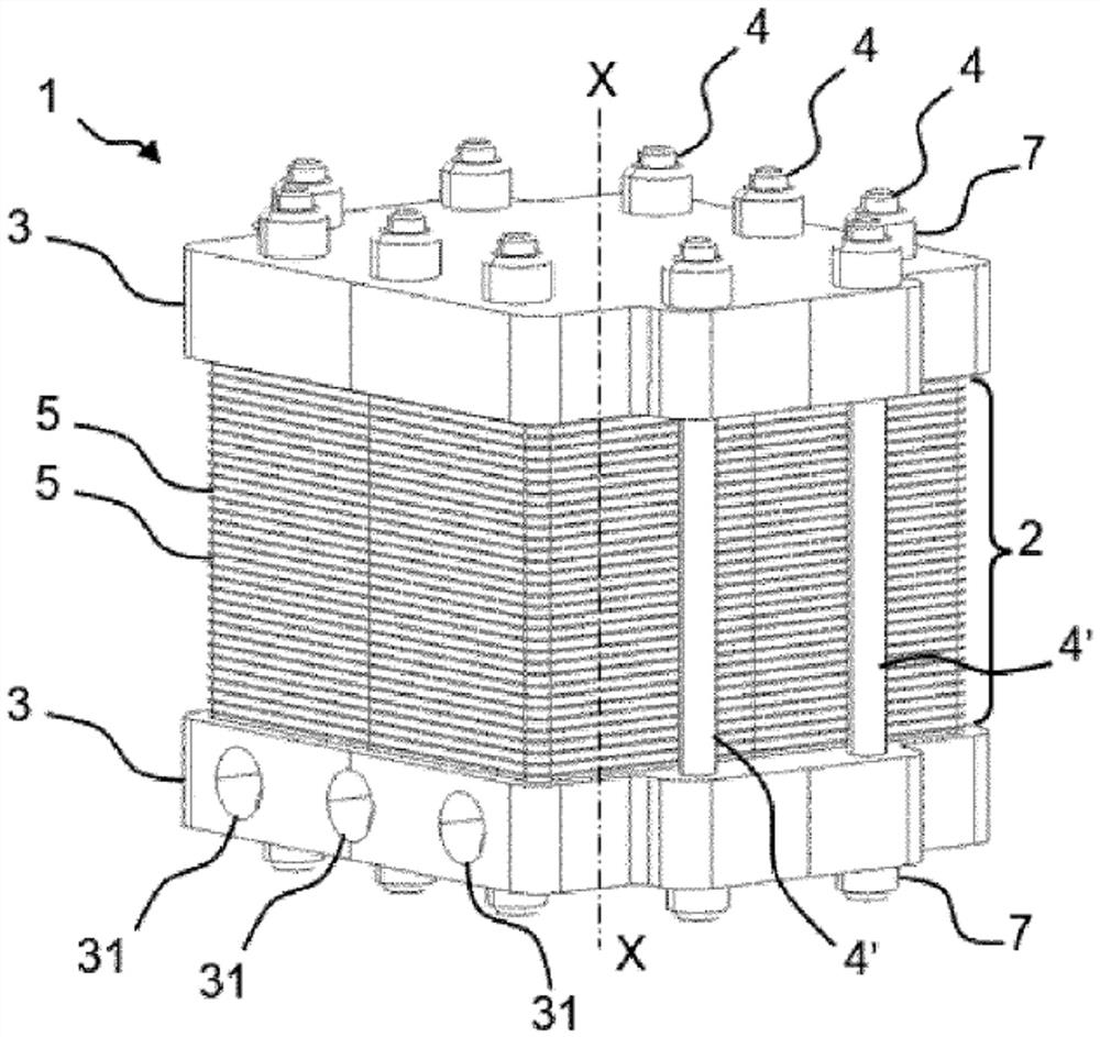
[0039] refer to image 3 , image 3 A fuel cell 1 generating electrical energy is generated by an electrochemical reaction in an embodiment of the present invention.

[0040]Traditionally, a different fluid is circulated in a fuel cell 1, thereby reacting electric energy. This reaction can be specifically a redox reaction between oxygen and hydrogen. Therefore, the fuel cell 1 is supplied with oxygen and hydrogen. The redox reaction also produces water, which is discharged from the fuel cell 1. In a preferred embodiment, the fuel cell 1 is a high temperature fuel cell, wherein the water produced by the reaction is a turbine. In fact, as will be described later, the vapor water is easy to discharge. The fuel cell 1 is also supplied with a coolant to release heat generated by the electrochemical reaction. The coolant is a heat transfer fluid, such as oil or water, which can be mixed with an additive.

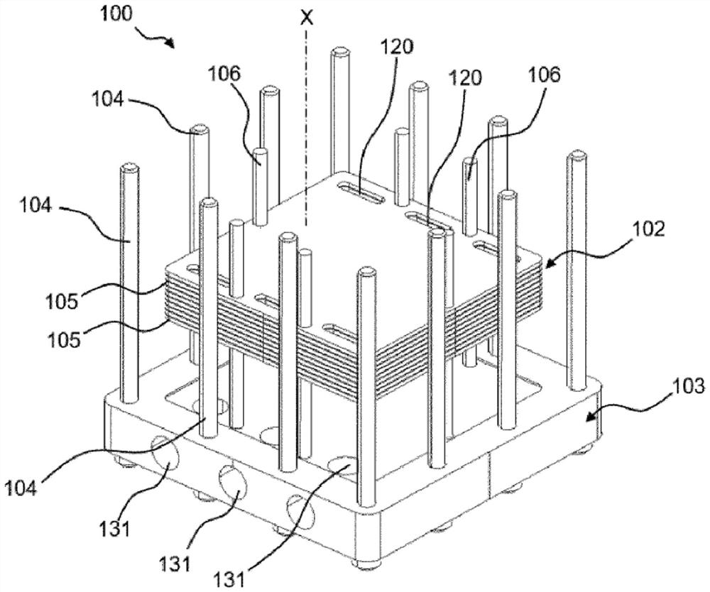
[0041] like image 3 and Figure 4 As shown, the fuel cell 1 includes a battery stack...


PUM


Abstract

A fuel cell (1) comprises a stack (2) which comprises a plurality of cells (5), each cell (5) comprising a plurality of fluid flow openings (50) aligned in parallel to form a plurality of fluid flow lines in the stack (2), two end plates (3) placed at the ends of the stack (2) and at least one traction member (4) connecting the end plates (3) to each other in order to compress the stack (2), the traction member (4) being mounted in a fluid flow line (20) of the stack (2).

Description

Technical field [0001] The present invention relates to fuel cells, especially in the aerospace field. Background technique [0002] The fuel cell produces electrical energy through an electrochemical reaction between different fluids. Traditionally, electrical energy is generated by providing hydrogen and oxygen to the fuel cell and reacting them in a fuel cell. [0003] like figure 1 As shown, the fuel cell 100 includes a battery stack 102, and the battery stack 102 includes a plurality of batteries 105 that are stacked along the stacked axis X. Each battery 105 includes a plurality of fluid cycle openings 150. The fluid circulation opening 150 of each battery 105 is contacted in a direction parallel to the stacked axis X to form a plurality of fluid circulation pipes 120 in the battery stack 102. The battery stack 102 of the battery 105 enables fluid to perform electrochemical reactions. like figure 2 As shown, each battery 105 is panel shape, and the board includes a fluid cy...

Claims


Application Information

Patent Timeline
Patent Type & Authority Applications(China)
IPC IPC(8): H01M8/2483H01M8/247H01M8/248
CPCH01M8/2483H01M8/248Y02E60/50
Inventor 罗曼·昆顿让-巴布提斯·卓莉诗西奥菲尔·霍德
Owner SAFRAN POWER UNITS
Why Eureka
Try Eureka