
a locking device

A locking device and conveying pipeline technology, applied in positioning devices, manufacturing tools, parts of grinding machine tools, etc., can solve the problems of easy damage of parts, cumbersome and inconvenient operation of moving brackets, etc.

Active Publication Date: 2022-04-26
SHOUGANG JINGTANG IRON & STEEL CO LTD
View PDF4 Cites 0 Cited by
  • Summary
  • Abstract
  • Description
  • Claims
  • Application Information

AI Technical Summary

Problems solved by technology

[0003] The invention provides a locking device, which solves or partially solves the technical problems in the prior art that the mobile bracket is cumbersome to operate, the parts are easily damaged, and it is not easy to operate.

Method used


Image

  • a locking device
  • a locking device
  • a locking device

Examples


Embodiment Construction

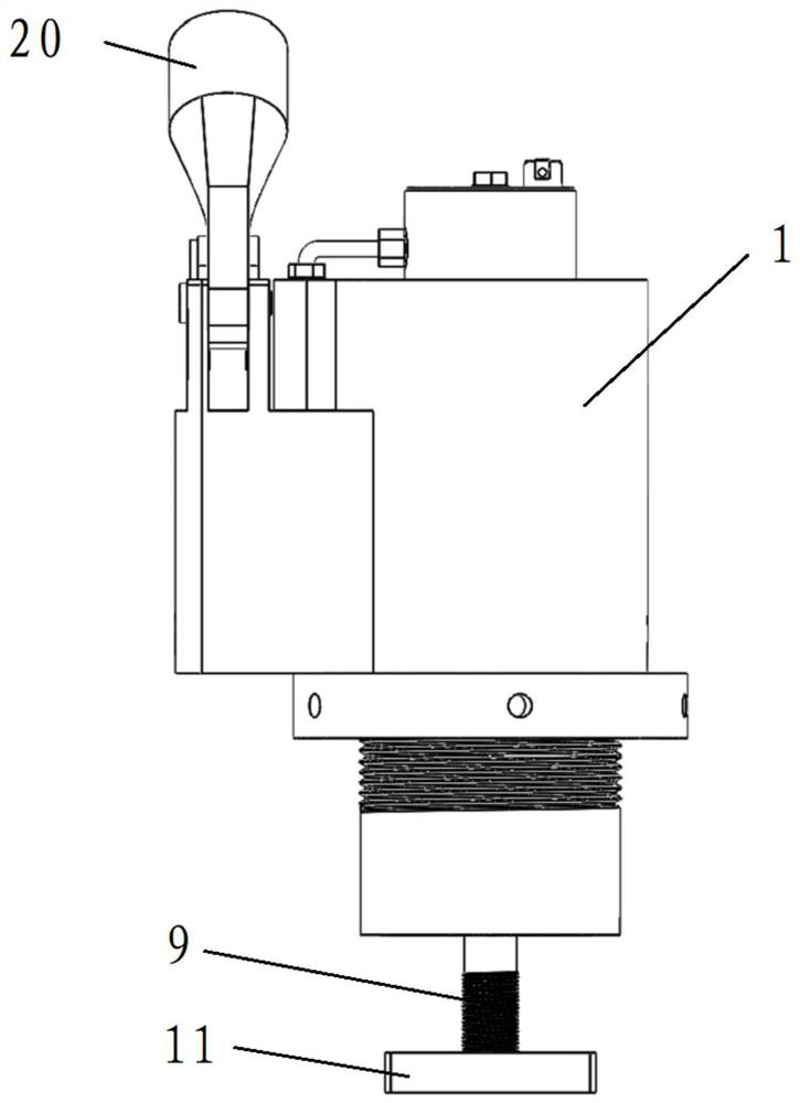
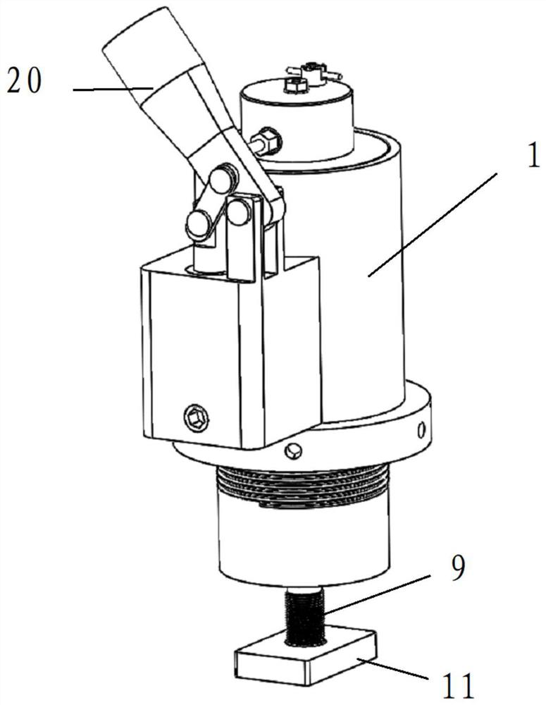
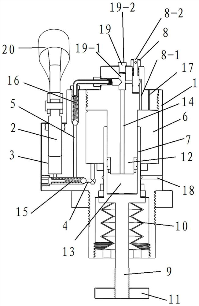
[0020] see Figure 1-3 , a locking device provided by an embodiment of the present invention includes: a housing 1, a pressurized piston 2, a pressurized cylinder 3, a first delivery pipeline 4, a second delivery pipeline 5, an oil chamber 6, a telescopic piston cylinder 7, a telescopic Piston 9, disc spring 10, locking block 11 and decompression mechanism 8.

[0021] The pressurizing cylinder 3 is fixedly arranged in the housing 1 , and the pressurizing piston 2 is slidably arranged in the pressurizing cylinder 3 .

[0022] The oil chamber 6 is fixedly arranged in the housing 1 .

[0023] The oil inlet of the first delivery pipeline 4 communicates with the oil chamber 6 , and the oil outlet of the first delivery pipeline 4 communicates with the pressurizing cylinder 2 .

[0024] The telescopic piston cylinder 7 is slidably arranged in the housing 1 .

[0025] The oil inlet of the second delivery pipeline 5 communicates with the first delivery pipeline 4 , and the oil outle...


PUM


Abstract

The invention discloses a locking device, which belongs to the technical field of roll grinding machines. The locking device includes: a pressurized cylinder and a fixed arrangement in the casing, a pressurized piston slidably arranged in the pressurized cylinder; an oil chamber fixedly arranged in the casing; the oil inlet of the first delivery pipeline and the oil chamber The oil outlet of the first delivery pipeline is connected with the pressurized cylinder; the telescopic piston cylinder is slidably arranged in the housing; the oil inlet of the second delivery pipeline is connected with the first delivery pipeline, and the oil outlet of the second delivery pipeline The port is connected with the telescopic piston cylinder; the first end of the telescopic piston is fixedly connected with the telescopic piston cylinder, and the second end of the telescopic piston passes through the housing to connect with the locking block; the disc spring is sleeved on the telescopic piston, and the disc spring is set on the housing Inside the body; the oil inlet of the decompression mechanism communicates with the second delivery pipeline, and the oil outlet of the decompression mechanism communicates with the oil cavity. The locking device of the present invention can reduce labor intensity, avoid damage to components, and facilitate operation.

Description

technical field [0001] The invention relates to the technical field of roll grinders, in particular to a locking device. Background technique [0002] At present, the center frame mechanism of Huachen 8480 grinding machine is locked with four bolts. Due to the variety of grinding rolls, the position of the center frame needs to be changed frequently. Every time the support is moved, it is necessary to use a wrench to loosen the bolts. Fasten the four bolts with a wrench, which increases labor intensity and affects work efficiency. Moreover, due to the lack of elasticity of the bolts, when the center frame mechanism is hit by the rollers, it cannot produce a cushioning effect, which is likely to cause damage to the track and the center frame components. The space around the center frame is narrow, and it is limited by the space when tightening the bolts. It is inconvenient to use a torque wrench with an afterburner rod, which makes it difficult for grinders with little stren...

Claims


Application Information

Patent Timeline
Patent Type & Authority Patents(China)
IPC IPC(8): B23Q3/06B24B41/06B24B41/00
CPCB24B41/06B24B41/007B24B41/00
Inventor 刘学生解士玲李旭李保卫谭禄禄曹剑
Owner SHOUGANG JINGTANG IRON & STEEL CO LTD
Learn More