A memory alloy locking and releasing mechanism

A memory alloy, locking and releasing technology, applied in the field of releasing and locking, can solve the problems of poor consistency of locking or releasing state, limited movement range of the locked mechanism, no degree of freedom, etc., to reduce parts batches dimensional error, long service life, and the effect of reducing the impact force

Active Publication Date: 2021-11-16
BEIJING INST OF CONTROL ENG
View PDF7 Cites 0 Cited by
  • Summary
  • Abstract
  • Description
  • Claims
  • Application Information

AI Technical Summary

Problems solved by technology

[0005] First, at the moment of unlocking the lock and release device of pyrotechnics, the impact force generated by deflagration reaches a hundred times the acceleration of gravity, and there is a defect that the unlocking impact is large
[0006] Second, each set of pyrotechnic locking and releasing devices can only realize the deflagration release function once. When there are multiple release requirements, it is necessary to constantly replace new pyrotechnic locking and releasing devices, and the cost of use is relatively high.
[0007] Third, after the pyrotechnic product is locked and the release device is unlocked and released, the locked mechanism mostly does not have the freedom to move along the tangential direction parallel to the pressing surface at the locking position, so that the locked mechanism can move in the locked position limited range
[0008] Fourth, due to factors such as processing errors, installation errors, and material batch differences of different batches of pyrotechnics locking and releasing devices with one-time detonation and release functions, there are deficiencies such as poor consistency in locking or releasing states

Method used


Image

  • A memory alloy locking and releasing mechanism
  • A memory alloy locking and releasing mechanism
  • A memory alloy locking and releasing mechanism

Examples


Embodiment Construction

[0035] In order to make the solution of the present invention clearer, the present invention will be further described below in conjunction with the accompanying drawings and specific embodiments:

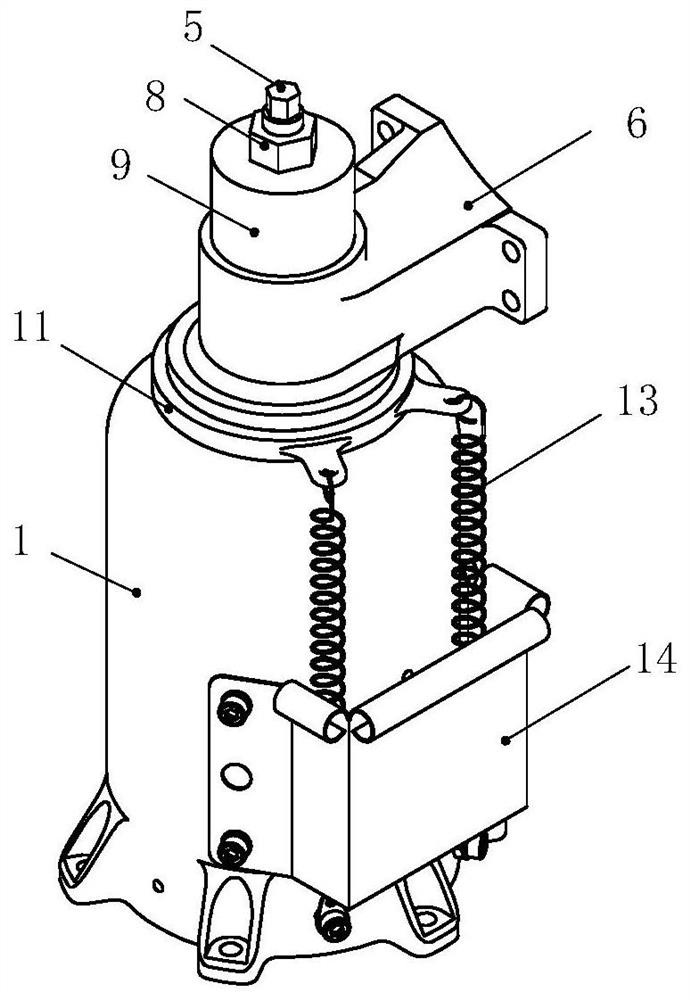
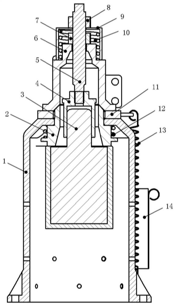
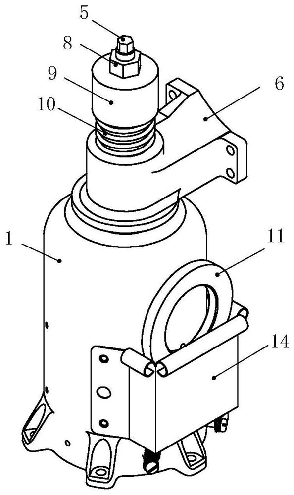
[0036] Such as Figure 1~6 As shown, a memory alloy locking and releasing mechanism includes a locking seat 1, a pressing cone 2, a memory alloy unlocker 3, a separation cap 4, a locking rod 5, a locking arm 6, a locking nut 7, an anti-off Nut 8, anti-off cap 9, anti-off spring 10, separation pad 11, separation spring 12, extension spring 13, storage cover 14.

[0037] The locking seat 1 is a housing with through holes at both ends, and one end of the housing is provided with a through hole for piercing the compression cone 2, the memory alloy unlocker 3, and the separation spring 12, and is also provided with a flange for installation and fixing , the other end of the housing has a shaft shoulder for piercing and installing the compression cone, the outer surface of the housing h...


PUM


Abstract

The invention discloses a memory alloy locking and releasing mechanism. The invention adopts a locking seat, a separation spring, a memory alloy unlocker, a pressing cone, a separation pad, a locking arm, a separation cap, a locking rod, an anti-off cap, an anti- The cooperation of the release spring realizes the small impact force of unlocking and releasing, repeatable locking and unlocking and releasing, after unlocking, the locking arm has degrees of freedom along the normal direction and tangential direction of the pressing surface at the same time, and the unlocking process The purpose of no smoke and other redundant objects makes up for the defects of traditional pyrotechnics-driven unlocking devices.

Description

technical field [0001] The invention relates to a mechanism driven by a memory alloy, which belongs to the technical field of locking and releasing. Background technique [0002] Locking and releasing are usually the fixing and releasing operations of a mechanism with at least one degree of freedom of movement. The purpose of locking is to constrain and fix the moving parts of the locked mechanism to avoid collisions or the locked mechanism under external excitation. Resonance occurs. The purpose of release is to release the movable parts of the locked mechanism, so that the locked mechanism can obtain the original number of degrees of freedom before being locked. [0003] In recent years, common locking and releasing devices at home and abroad all adopt pyrotechnic locking and releasing devices. The locking principle is to use bolts and nuts to compress and the principle of concave-convex cooperation on both sides of the pressing surface to restrain the locked mechanism. ...

Claims


Application Information

Patent Timeline
Patent Type & Authority Patents(China)
IPC IPC(8): F16B1/00F16B1/04
CPCF16B1/04F16B2200/77
Inventor 张述卿张强刘继奎叶壮马婷婷蒋俊朱林林刘雪鹏刘巍李臣
Owner BEIJING INST OF CONTROL ENG
Why Eureka
Try Eureka