
Injection molding machine with material sorting structure at feeding port and use method of injection molding machine

A feed port, injection molding machine technology, applied in chemical instruments and methods, solid separation, sieving and other directions, can solve the problems of screening efficiency, affecting production efficiency, unfavorable screening, etc., to achieve the effect of improving efficiency

Inactive Publication Date: 2021-08-17
王建青
View PDF0 Cites 9 Cited by
  • Summary
  • Abstract
  • Description
  • Claims
  • Application Information

AI Technical Summary

Problems solved by technology

[0003] Most of the existing injection molding machine particle raw materials are screened by sieves, and the size difference of the injection molding machine raw material particles is small. After screening, most of the unqualified particles are stuck in the sieve holes, which is not conducive to subsequent screening and needs to be manually removed. , seriously affecting production efficiency
[0004] To this end, an injection molding machine with a material sorting structure at the feed port and its use method are provided to solve the problem of screening efficiency

Method used


Image

  • Injection molding machine with material sorting structure at feeding port and use method of injection molding machine
  • Injection molding machine with material sorting structure at feeding port and use method of injection molding machine
  • Injection molding machine with material sorting structure at feeding port and use method of injection molding machine

Examples


Embodiment Construction

[0031] The following will clearly and completely describe the technical solutions in the embodiments of the present invention with reference to the accompanying drawings in the embodiments of the present invention. Obviously, the described embodiments are only some, not all, embodiments of the present invention. Based on the embodiments of the present invention, all other embodiments obtained by persons of ordinary skill in the art without making creative efforts belong to the protection scope of the present invention.

[0032] see Figure 1 to Figure 7 , the present invention provides a technical solution:

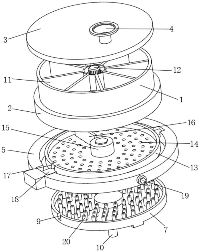
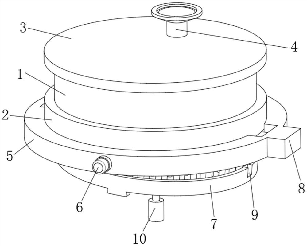
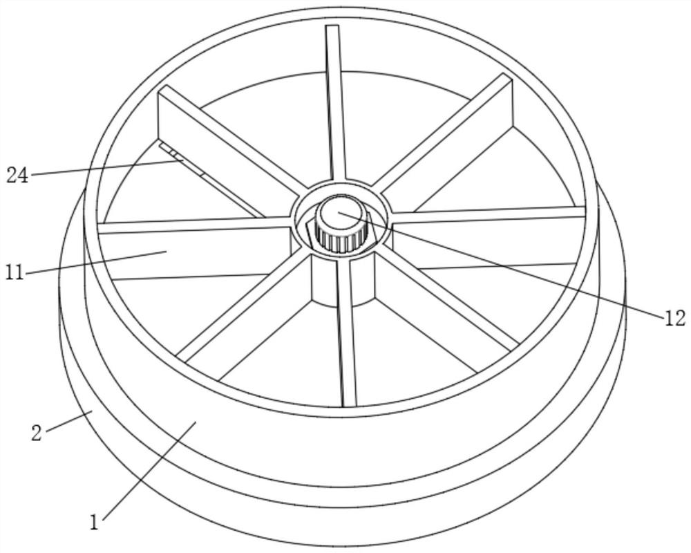
[0033] An injection molding machine with a material sorting structure at the feed port, comprising a feed frame 1, the upper end of the feed frame 1 is provided with a cover plate 3 with a feed funnel 4, and the inner cavity of the feed frame 1 is provided with a rotating The multiple groups of fan-shaped rotating plates 11 distributed in the installed circular array, th...


PUM


Abstract

The invention relates to the technical field of feeding of injection molding machines, in particular to an injection molding machine with a material sorting structure at a feeding port and a using method of the injection molding machine. The injection molding machine comprises a feeding frame, wherein a cover plate with a feeding hopper is arranged at the upper end of the feeding frame, and multiple sets of fan-shaped rotating plates which are rotationally installed and distributed in a circumferential array manner are arranged in an inner cavity of the feeding frame; and a fixed circular ring frame is arranged at the lower end of the feeding frame, and a rotating sieve plate for limiting the rotating angle is arranged in an inner cavity of the fixed circular ring frame. The injection molding machine has the beneficial effects that the fan-shaped rotating plates are arranged, so that the feeding amount is controlled, then raw materials are efficiently sorted through cooperation of a scraping plate and a screening plate, and the purpose of automatic feeding is achieved in cooperation with an obliquely-arranged blanking disc; and by arranging the rotary sieve plate, the purpose of ejection cleaning is achieved through limiting rotation when sieve holes are cleaned, the purpose of automatic discharging is achieved through angle inclination of the sieve plate during cleaning, and the cleaning efficiency of the sieve plate is greatly improved.

Description

technical field [0001] The invention relates to the technical field of feeding materials for injection molding machines, in particular to an injection molding machine with a material sorting structure at a feeding port and a method for using the same. Background technique [0002] Injection molding machine is an injection molding machine used for plastic parts. The injection molding machine heats and melts granular raw materials and injects them into the mold, and then cools and shapes them. During the heating and melting process, the size of the particles directly affects the melted raw materials. quality. [0003] Most of the existing injection molding machine particle raw materials are screened by sieves, and the size difference of the injection molding machine raw material particles is small. After screening, most of the unqualified particles are stuck in the sieve holes, which is not conducive to subsequent screening and needs to be manually removed. , seriously affect...

Claims


Application Information

Patent Timeline
Patent Type & Authority Applications(China)
IPC IPC(8): B29C45/18B29B13/10B07B1/50
CPCB07B1/50B29B13/10B29C45/18
Inventor 王建青
Owner 王建青
Learn More